About Contours
Contours, or lines of equal elevation, can be toggled on and off. The
contours are generated from the set of
LIDAR
points that are drawn in the map or (viewer window) or from the
TIN
surface that is displayed in the map (or viewer window). Contours
are mutually exclusive from the
Draw Type
setting (e.g., points, TIN, etc.), thus contours can be displayed
individually in the map or viewer window.
By default, the contour interval is system calculated. The properties
that control the contour interval, as well as the symbols used for
the intermediate and index contours, can be modified using the Contour
Legend property page. See
The
Contour Legend Property Page for more information.
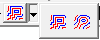
When displaying contours, you can use the regular Display Contours
setting, which can have definitive corners and edges; or you can use
the Smooth Contours settings, which uses a corner vertex spacing to
round, or smooth, the contour corners. This corner vertex spacing
number can also be set on the Contour Legend Property Page. If you
are zoomed out far in your map or viewer, you may not see a vast difference
between regular contours and smooth contours, but when you zoom in
significantly, you will see the difference.
 or
Smooth Contours
or
Smooth Contours 
 setting
is used, check that the number of points is not exceeding
the Maximum Points to TIN/Contour setting
in the Performance Options
tab of the Properties dialog box for
the viewer. Click the Properties
setting
is used, check that the number of points is not exceeding
the Maximum Points to TIN/Contour setting
in the Performance Options
tab of the Properties dialog box for
the viewer. Click the Properties  button to display the Properties dialog
box, and then find the setting on the Performance
Options tab.
button to display the Properties dialog
box, and then find the setting on the Performance
Options tab.