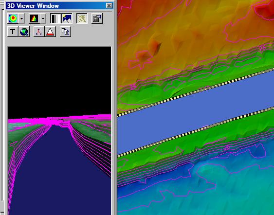
The Retaining Wall Conflation Method is used to create 3D geometry that
can be used as breaklines that enforce
vertical surfaces within the LIDAR
surface.
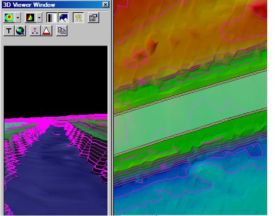
The retaining wall method assigns elevations from the LIDAR surface to
a bottom and top of wall lines. The bottom and top wall lines are stored
in the output geometry as multi-part features where the bottom and top
line are parallel to each other at a very small distance. The lines are
not exactly equal for a variety of reasons. Coincident lines would create
vertical triangles in the triangulated
surface that use the geometry as breaklines thus resulting in undefined
slope conditions. Another reason to create two lines, one representing
the bottom of the wall and the other the top, is for the storage of 2
elevation values per vertex which would be problematic.
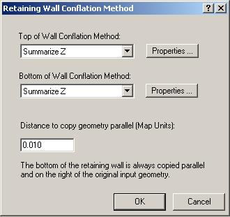
The bottom and top lines are assigned elevation values from a conflation
method. The conflation method assigned to each line can be different or
can be setup differently by modifying the conflation method's properties.
The distance that the bottom wall line is copied from the original line
is configurable. The direction of which wall lines are drawn is significant
because the bottom wall is always copied on the right of the input line.
So if all lines are drawn in the same direction, then the bottom will
end up on the same side, thus edge matching other bottom wall lines. If
two lines are drawn in the opposite direction of each other (i.e., "FROM"
snaps to "FROM" or "TO" snaps to "TO") then
the bottom wall line is copied on different sides of the lines causing
problems or unexpected results when using as breaklines.