We do a significant amount of Research and Development (R&D) in drone mapping. Our AV-900 rotary wing system has an L1/L2 Global Navigation Satellite System (GNSS) that we run in the Post-Processed Kinematic mode. This gives us the location of the AV-900 Survey System antenna to within a few centimeters relative to a local base station. This technique is commonly called Direct Geopositioning since, in theory, you can generate accurate mapping products with minimal ground control points.
It is very important to realize that direct geopositioning is not at all the same as having Ground Control Points (GCP). In direct geopositioning, we are estimating the focal center of the camera using offsets from the GNSS antenna (so called “lever arms”). Thus we know the approximate location of the camera at the time of the exposure (this also requires a trigger signal called the Mid Exposure Pulse, MEP, which is a whole other story!). We do not know the orientation (pitch, yaw and roll) unless we have augmented our GNSS with an orientation measuring device. With GCPs, we know the correspondence between image points and ground points from which we derive the location and orientation of the camera at the time of exposures. I use a rule of thumb that if all goes right, your lever arms are exact and you are using a camera gimbal, direct geopositioning will be within about a factor of 3 of the accuracy of using well laid out ground control (that is, the GCP project will have approximately 3x the accuracy of the PPK project). Now these are really just rules of thumb so do not take them literally. The most accurate configuration is direct geopositioning augmented by GCPs since this gives not only a close a priori estimate of the camera location at each exposure (from the GNSS PPK) but also ground points to tie down the model.
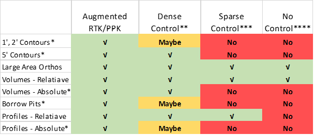
We are assembling some best practices for small Unmanned Aerial Systems (sUAS) or drone mapping. Table 1 is an example of the type of information we are assembling. Do not take the data in this table literally – it is a work in progress‼ However, I do believe the relative comparison between the types of control you need for various sUAS mapping scenarios is approximately correct.
- For all scenarios, a “good” calibrated camera is assumed
- “Absolute” means tied to a Spatial Reference System (e.g. Network)
- *Debiasing of Z is assumed (requires a known vertical reference)
- **A GCP such that circles of radius 300’ centered on each GCP will touch (e.g. nominally 600’ apart)
- ***A GCP such that circles of radius 500’ centered on each GCP will touch (e.g. nominally 1,000’ apart)
- ****Cannot be tied to a Spatial Reference System
This sort of information is critically important to planning sUAS mapping missions if you are a service provider (or owner/operator) or if you are evaluating a service provider. For example, if you need 2’ contours and someone says they can do this with PPK and a single target at a base station, an alarm bell should go off! Remember, results are not going to vary a lot based on GNSS equipment since we are dealing with fundamental physics. However, good cameras do make a big difference.
As time goes on, we will refine this into a useable planning document. We also intend, in the long run, to add control planning guidance information into Reckon, our sUAS data collaboration portal. Until then, be very cognizant of how geopositioning will be carried out for your projects. Make very sure that you have a plan for independently testing the accuracy of the data that has been processed by having a few well know, photo-identifiable locations in the project that are unknown to the data processor. Remember, Trust but Verify!
Download Article: A Framework for Control Strategies
