A Conflation Task defines a set of procedures for digitizing features that extract elevations from a LIDAR surface. A conflation task can be configured to digitize points, polylines, and/or polygon features.
The Conflation Method assigned to the conflation task defines how elevations are populated onto the geometry for each feature.
LP360 Default Conflation Tasks
- Summarize Z
- Drape
- Downstream Constraint
- Retaining Wall
Summarize Z
Z values can be computed as a variety of counting, surface, or proximity operations. Z values can be computed on a per feature or vertex basis.
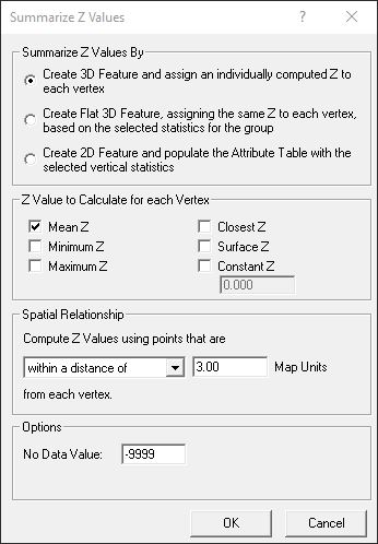
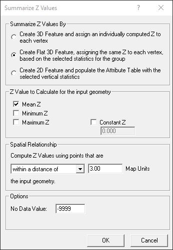
If using the by vertex option, one z value is calculated for each vertex in the input geometry. The z values for the by vertex option is stored with the feature geometry in the output dataset. There are two different conflation methods when it comes to storing the the elevation information on a by vertex option:
- Summarize Z Values by: Create 3D Feature and assign an individually computed Z to each vertex (For older versions of the software: computing one Z value for each vertex for the input geometry)
- Summarize Z Values by: Create Flat 3D Feature, assigning the same Z to each vertex, based on the selected statistics for the group (For older versions of the software: computing one Z value for the input geometry as a whole and store the Z value in the vertices)
Using the by feature option, one or more z values can be calculated for a single feature. The z value(s) are stored in the attribute table in the output dataset. There is only a single conflation method when it comes to storing the elevation information on a by feature option:
- Summarize Z Values by: Create 2D Feature and populate the Attribute Table with the selected vertical statistics (For older versions of the software: Computing one or more Z values for the input geometry as a whole)
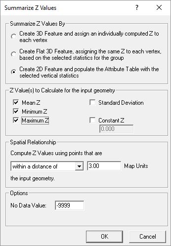
Summarize Z – Multiple Elevation values for the feature as a whole: Elevation information is stored in the attribute table
The following is the a list of z values the user can calculate for input geometry:
- Mean – Mean or average of the LAS point z values
- Maximum – Maximum of the LAS point z values
- Minimum – Minimum of the LAS point z values
- Constant Z – Same elevation value for all points as specified by user
- Surface Z * – TIN surface elevation from the LAS points
- Closest Z * – Closest LAS point z value to the vertex
* Per Vertex Only
Drape
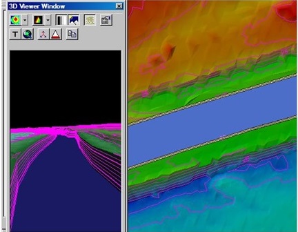
When a drape is performed over the LIDAR surface three conflation methods exist which define how the vertices within the output geometry are compiled:
- Pure Drape – creates a vertex in the output geometry for every intersection the input geometry makes with the triangulated LIDAR surface. The pure drape option best models the LIDAR surface within the output geometry.
- Create Vertex every X Map Unit(s) – creates a new vertex in the output geometry every X map units. Each vertex in the output geometry is assigned the elevation of the LIDAR surface directly beneath the vertex.
- Get Z for existing vertices – option does not create new vertices within the output geometry. The method assigns an elevation from the LIDAR surface to the existing vertices.
Downstream Constraint
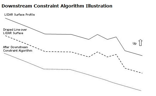
In order to ensure breaklines flow in a downstream direction a user would need to run downstream constraint on the files. The first step in this conflation task is to perform a drape of the geometry to the LIDAR surface. Once the input geometry is draped to the LIDAR surface, a downstream constraint algorithm is invoked on the output geometry to ensure that the vertices will flow downhill. The algorithm using linear interpolation will burn through uphill areas. The following diagram demonstrates how the algorithm works on a simple LIDAR surface profile.
Retaining Wall
The retaining wall method assigns elevations from the LIDAR surface to a bottom and top of wall lines. The bottom and top wall lines are stored in the output geometry as multi-part features where the bottom and top line are parallel to each other and at a very small distance. The bottom and top lines are assigned elevation values from a conflation method. The conflation method assigned to each line can be different or can be setup differently by modifying the conflation method’s properties.
*The distance that the bottom wall line is copied from the original line is user configurable. The direction of which wall lines are drawn is significant because the bottom wall is always copied on the right of the input line. So if all lines are drawn in the same direction, then the bottom will end up on the same side, thus edge matching other bottom wall lines. If two lines are drawn in the opposite direction of each other (i.e., FROM snaps to FROM or TO snaps to TO) then the bottom wall line is copied on different sides of the lines causing problems or unexpected results when using as breaklines.
What’s the difference between summarize z with surface z and drape with pure drape?
When using summarize Z with the surface Z option the existing vertices are assigned the TIN surface elevation formed from the LAS points at the same XY location as each vertex. Whereas, the Pure Drape method creates a vertex in the output geometry for every intersection the input geometry makes with the triangulated LIDAR surface. The pure drape option best models the LIDAR surface within the output geometry. Hence, the former method applies to original vertices only, and the latter will create additional vertices.