Building a Simple Corridor
We will use an example of building a road corridor. For this exercise, we have created a new project in the NAD 83, Zone 16 N meters horizontal coordinate system and ellipsoid, meters for the vertical system. To this project we added a reference raster layer and imported the Madison County Composite USGS Digital Raster Graphic that is located on your GeoCue Sample Data disk. This is depicted in the figure below:
The first step in designing the corridor is to sketch a GeoDraw line along the center of the Interstate spur since we don’t have a preexisting one. Simply select the GeoDraw Line command and draw a line. Our digitized road is shown in the figure below:
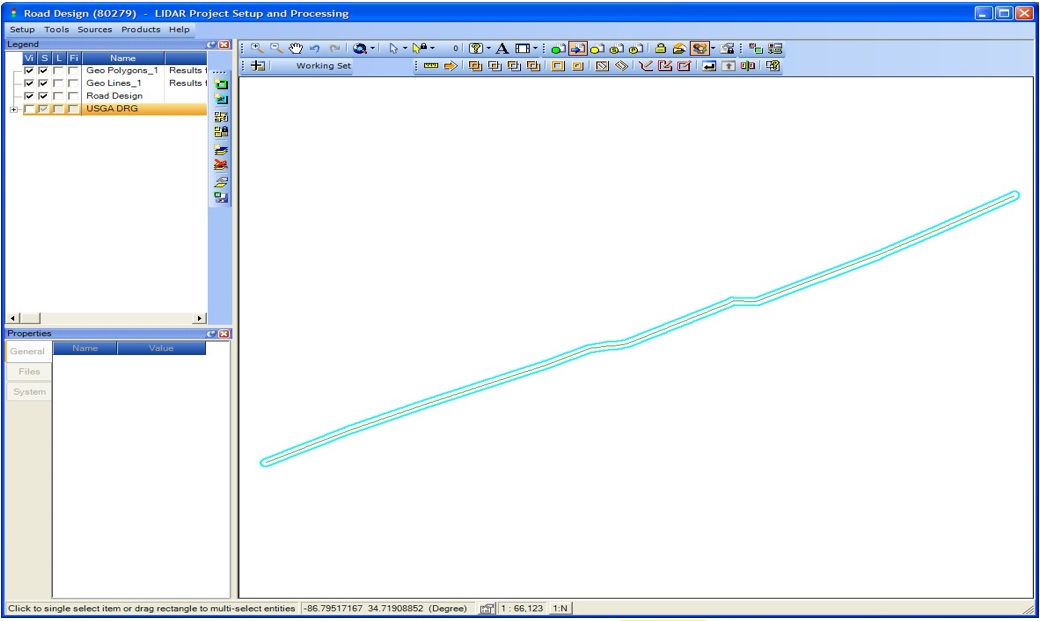
Next, we will build a polygonal corridor using the buffer command. Set the buffer size to the desired half width of your corridor. For our example, we wish to construct a corridor 200 meters wide (100 meters to each side of the road line). Thus, the Buffer Distance in the GeoAnalysis Options dialog is set to 100 meters. Now Select the line and press the Grow Buffer tool. This will construct a polygon whose center line is the digitized road and whose width is 200 meters. Our corridor is depicted in the figure below:
The final step of construction is to use this GeoAnalysis polygon as the template for constructing the final desired type of entity. This is accomplished by Selecting the corridor template and using the Create Entity command to create the desired type of GeoCue entity, using the placement method Selected Entities Geometry.
Partitioning a polygon
It is often necessary to partition an entity to reduce it to workable sized elements. An example might be partitioning a corridor project into LAS (elevation) segments for editing.
GeoCue provides a number of tools that can be used to subdivide polygons. In this section we will investigate the “segment” tool on the GeoAnalysis toolbar. The segment tool allows you to place entities that will act as the segmentor (knife, if you will) on a GeoAnalysis queue and use these entities to segment all selected entities. The result is a new set of GeoAnalysis entities (the items to be segmented act simply as a template – they are not actually changed).
We will use the road corridor GeoAnalysis entity of the previous section in this example. Draw a series of GeoAnalysis lines that cross the corridor at the locations where you want the segment boundaries to occur. Our example is depicted in the figure below:
Next Select the items that are to act as the Segmentors (the knife blades). In our example, these are the line segments that we just drew. Now add these to the GeoAnalysis Input Queue by pressing the Input Queue Enter button on the GeoAnalysis toolbar. This action will create a named queue (the name of which is GeoAnalysis Input Queue) and place all entities that were in the Selected state at the time the tool is pressed onto the queue.
Next Select the entity that is to be segmented by the entities in the queue. Finally, press Segment tool button on the GeoAnalysis toolbar. Note that it is a good idea to set the GeoAnalysis options to create a new layer. This makes it easier to segregate the results. Make note of the results layer name displayed in this dialog to locate the segments. The results of our example segmentation are displayed in the figure below:


