Contours can be generated from a TIN surface at specified intervals. The contours are saved to one of the three following file formats: shapefiles, DXF, or DGN. Contours are stored as 3D polylines for DXF and DGN file formats. You have a choice to save polylines as 3D or 2D when exporting to shapefiles, where the elevation is always stored as an attribute for each contour. Each index and intermediate contour is assigned a user-specified type code. The codes are stored as attributes for shapefiles. However, if exporting to DXF or DGN files, the contours are assigned to the layer or level respectively.
In addition to contour lines, annotation can be generated for index and/or intermediate contours. You can control posting frequency, as well as the length of contours to annotate. Similar to contour lines, annotation is assigned a user-specified type code that is stored as an attribute for shapefiles, but determines the layer or level for which text is assigned in the DXF or DGN file formats.
| Note: When generating annotation for shapefiles, points are stored in a shapefile named with an “_anno” suffix. Each point has text height and rotation values stored in the attribute table. |
Using Breakline Enforcements
As part of generating contours, breaklines may be used to enforce significant topographic breaks in the surface, such as stream centerlines or ridge lines. Breakline enforcement can significantly influence the aesthetics or functionality of a surface model. When exporting contours, the use of breaklines can provide a much more cartographic display of contour lines. Breakline sources can be any layer in the map that is suitable to be used as breaklines.
How to Export Contours
Exporting Contours
- Open the LP360 Export Wizard by clicking the Export LIDAR Data command on the LP360 toolbar. The Export Wizard dialog will open with the Step 1 of 3 page displayed.

- Click the arrow in the Export Type list and select Surface.

- Click the arrow in the Surface Method list and select the Triangulation (TIN) surface method.

- Enter a No-Data value for the underlying surface that is used to generate the contours.

- Ignore the cell size, as it is not used for exporting contours.

- If you are using breaklines, click Breakline Enforcement button. The Breakline Enforcement Property Page will open.

- On the Breakline Enforcement dialog, define which layers/sources to use as breaklines.

- Click OK to close the Breakline Enforcement dialog.
- On the Breakline Enforcement dialog, define which layers/sources to use as breaklines.
- If you selected the Inverse Distance Weighted (IDW) export surface method, do the following:
- Enter a Power greater than zero.

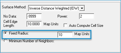
- Select Fixed Radius and enter a radius value greater than zero Map Units.

OR
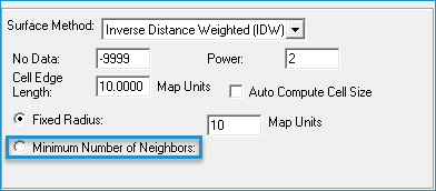
Select Minimum Number of Neighbors and enter the minimum number of points to use to interpolate elevations.
OR
Also, if you are using the Minimum Number of Neighbors option, click the Maximum Search Window check box if you want to specify a maximum search window size, and then enter the value in Map Units. If you leave this check box unselected, the system will determine a maximum search window size using average point densities of the LIDAR data.
- Enter a Power greater than zero.
- In the Surface Attribute to Export list, select Contour. A Contours tab will appear next to the Surface tab. Select the Contours tab, and then the General tab.

- Select a file format in the Contour File Type list.

- If you select the shapefile format, select the Export as 3D Shapes checkbox if you want the shapefile to contain 3D shapes. If you leave this option unselected, 2D shapes will be stored within the shapefile. (An elevation will be stored as an attribute for each contour regardless of this setting).

- Enter a Contour Interval greater than zero.

- Enter a length in Map Units for the shortest contour you wish to export to the file. A zero input will export all contours.

- Enter the number of contours (greater than zero) between each index contour in the Contour Intervals per Index Contour.

- Enter a type code for Index Contours. This number will be assigned to each index contour in the attribute table. For DXF and DGN formats, this code corresponds with the layer or level for each entity or element respectively.

- Input a type code for intermediate contours in the Intermediate Type Code box. This number will be assigned to each intermediate contour in the attribute table. For DXF and DGN formats, this code corresponds with the layer or level for each entity or element respectively.

- The user may turn on Smooth Contours by checking the appropriate box. The Smoothing Distance setting determines the size of the spacing, in Map Units, between vertices used to give contour corners smoother edges.

- Click the Annotation tab.

- If exporting annotation, select the Export Annotation checkbox. If you are not exporting annotation, you can skip to step 9. The remaining options are for defining the annotation export.

Tip: When exporting to annotation using the shapefile format, annotation is exported as points in a file with a suffix of “_anno”. Each point has the text height and rotation values (radian and degree) stored in the attribute table. - Enter a Posting Frequency greater than zero in map units.

- Enter the Shortest Contour to Annotate as a percent of the Posting Frequency. A zero input will produce annotation for all contours.

- Enter the Text Height (greater than zero) in map units.

- Enter a type code for the annotation in the Annotation Type Code. This number will be assigned to each annotation in the attribute table. For DXF and DGN formats, this code corresponds with the layer or level for each entity or element respectively.

- Select the Export Intermediate Annotation check box if you want to export annotation for the intermediate contours. If you leave this option unselected, the annotation will NOT be generated for intermediate contours.

- Select a file format in the Contour File Type list.
- In the Surface Attribute to Export list, select any other attributes you want to export.
Notes: For exporting the slope, clicking Slope in the list displays a tab next to the Surface tab. Click the Slope tab and click Calculate in Percent if you want the slope calculation to be in percents. If not selected, the slope is calculated in degrees. For exporting the hillshade attribute, clicking Hillshade in the list displays a tab next to the Surface tab. Click the Hillshade tab and enter the azimuth and altitude of the sun/light source. The default values are set up to produce a standard shaded relief map. For exporting contours, click Contours in the list and follow the instructions for exporting contours. - On the page for the Surface tab, click the arrow on the Export Format list, and select ASCII Raster, Binary Raster, or ASCII XYZ.

- If exporting to ASCII XYZ text files, click the Include Headers in File(s) checkbox if you want to include the column names for each exported attribute on the first line of the text file. Then select the Delimiter (i.e., comma, space, or tab) to use for separating the columns in the text file.

- Click Next to go to the next step in the Export Wizard.


