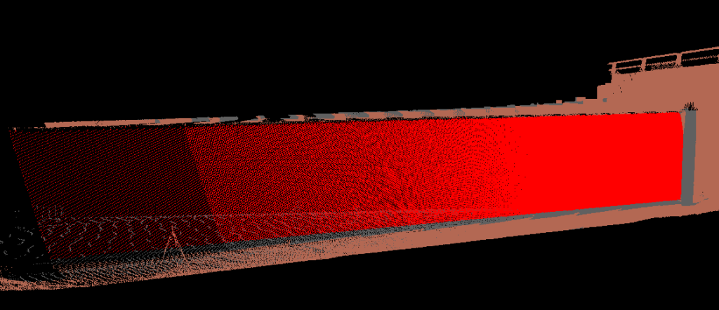
It may be desired to create a grid of points for a vertical feature, such as a wall in LP360 or True View Evo. This could be used to detect the change of a set of gridded points, that are static in Z, which could potentially shift planimetrically over time. The following outlined workflow will review the process for creating this grid of points and how to utilize these as a reference for comparison with future surveys. The workflow contains several steps: isolating the vertical feature from the dataset, determining the azimuth and slope for rotating the feature, rotating feature, creating point grid, and using the grid as a reference.
1. Defining the Wall Area
The first step of this process is isolating the wall feature from the rest of the dataset. The user can easily accomplish this using LP360 manual classification tools. Be sure that no other features are present in the class used for classification: ground, vegetation, etc. Use the Live View Filter to display only the classified wall section.
Once the wall has been classified, export only the wall points into a separate file. Make sure that this file is displayed and the active LAS layer moving forward with the remainder of processing.
2. Planar Statistics Point Cloud Task
Determine the azimuth and slope for the vertical feature points by running the Planar Statistics Point Cloud Task on a section of the wall. These values will be utilized for the next step of the process.
3. Rotating the Data – Affine Transform LAS Point Cloud Task
In order to properly generate a grid of points in LP360, the vertical feature must be rotated where the planar surface face has a horizontal orientation. To accomplish this, the Affine Transform LAS PCT can rotate the wall to satisfy this requirement. This initial rotation can be performed in a single rotate step by:
- Enter the Planar Stats slope value into the Rotate Y field
- Subtract the Planar Stats azimuth value from 90, flip the sign (e.g. – positive to negative) and enter the value into the Rotate Z field
- Run on project to create a new point cloud feature with the desired rotation applied
4. Generate Grid of Points
Based on this newly rotated wall dataset, the user can generate a grid using the Grid Generator PCT. Settings are as follows:
- Choose the desired cell size
- Grid Out Type: 3D Points
- Input Geometry Clipping: Full Grid
- Clip to Input LAS Data: Clip to Input LAS Data
- Choose output location
Once a grid is generated, clean up (delete) the excess points outside of the wall area using LP360 feature edit tools. Use the feature edit tool auto-z function to conflate the grid to the wall surface. Now the user should have an initial grid of points for the wall surface.
5. Grid as a reference
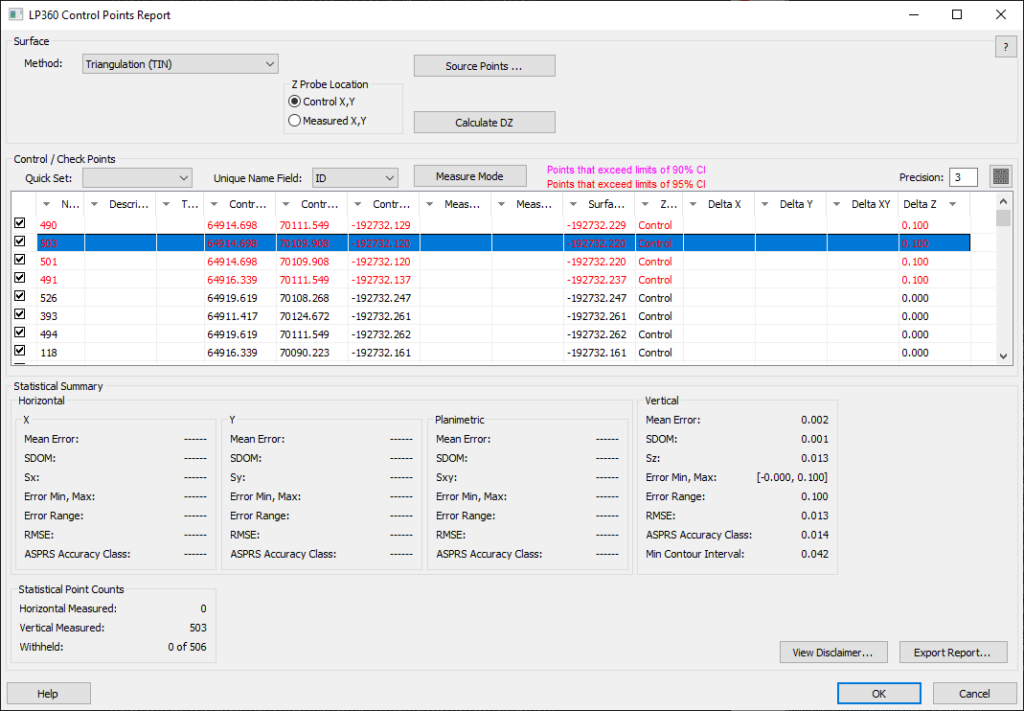
This grid can be used as a reference for planimetric temporal change detection. The initial grid will be the baseline. The point clouds from additional surveys would use steps 1 and 3 (reusing the values calculated from step 2) and use the grid generated from the initial survey (step 4) to compare the change between surfaces using the control report function. This would allow the user to calculate the amount of horizontal movement that the wall is exhibiting over time.


