
This article provides step-by-step instructions to mount TrueView sensors to the DJI Matrice 300 / Matrice 350 drone, including PLI and smart dovetail adapters. Follow these procedures for safe, secure, and optimal installation.
| Part number : FTV1000877A00T (Antenna mount included in this kit) |
Payload compatibility
All Trueview payloads equipped with a PLI-type adapter (4 pegs), up to 2.7kg.
Installation video
Included components
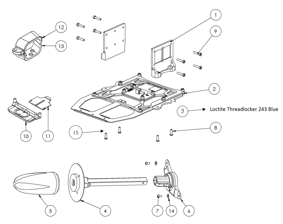
- M300 leg plate (2)
- M300 PLI Carbon Fiber Mounting Plate
- Loctite Threadlocker Blue 243
- Antenna mast assembly (with coaxial cable)
- Antenna (included with payload, may differ from image)
- Antenna mast plus base
- M3 x 6 mm button head screws (2)
- M3 x 12mm button head screws (4)
- M3 x 14 mm socket head screws (8)
- M300 IR cover
- M300 IR tab
- M300 Coax adapter – top
- M300 Coax adapter – bottom
- M3 washer (2)
- M2.5 x 6 Button Head Hex Screw (2)
Required tools
- 2mm hex screwdriver
- 2.5mm hex screwdriver
Installing the Payload Adapter
The following steps summarize how to integrate the drone side payload interface:
- Remove the four (4) M3x10mm screws (retain these screws for future use) holding the leg of the DJI M300 drone.
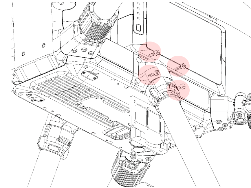
2. Insert the M300 aluminium leg plate between the leg and the body of the drone.
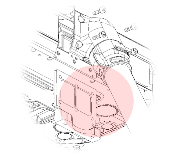
3. Screw in the four (4) new M3x14 mm socket head screws (supplied) to secure the leg into place.
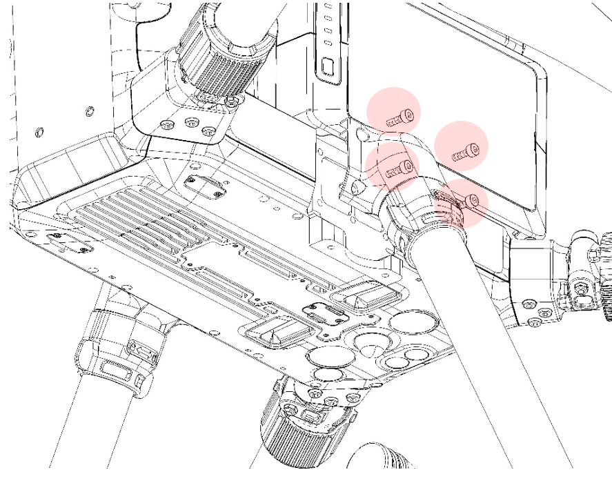
4. Repeat Step 1 through Step 3 on the other side of the drone
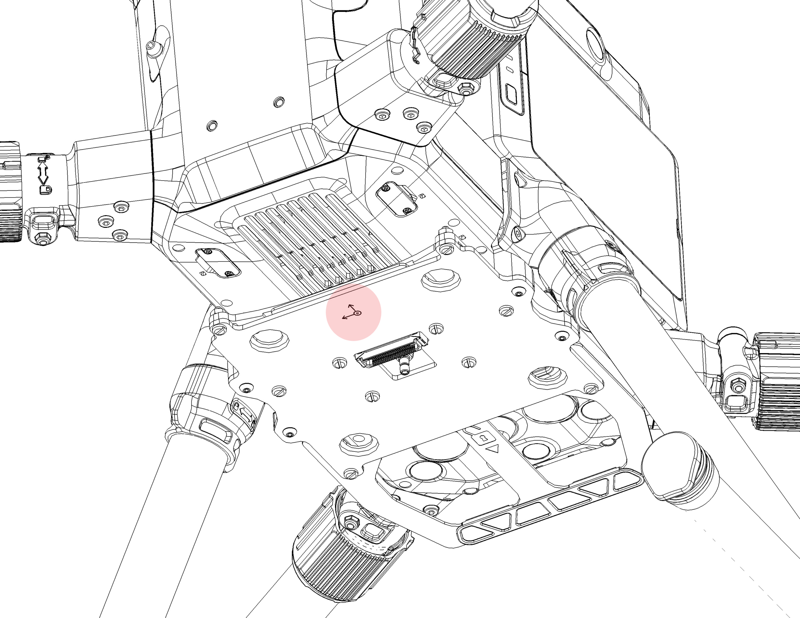
5. From the bottom side of the drone, attach the main plate assembly to the M300 leg plate fixation points using four (4) new M3x12mm screws (supplied).
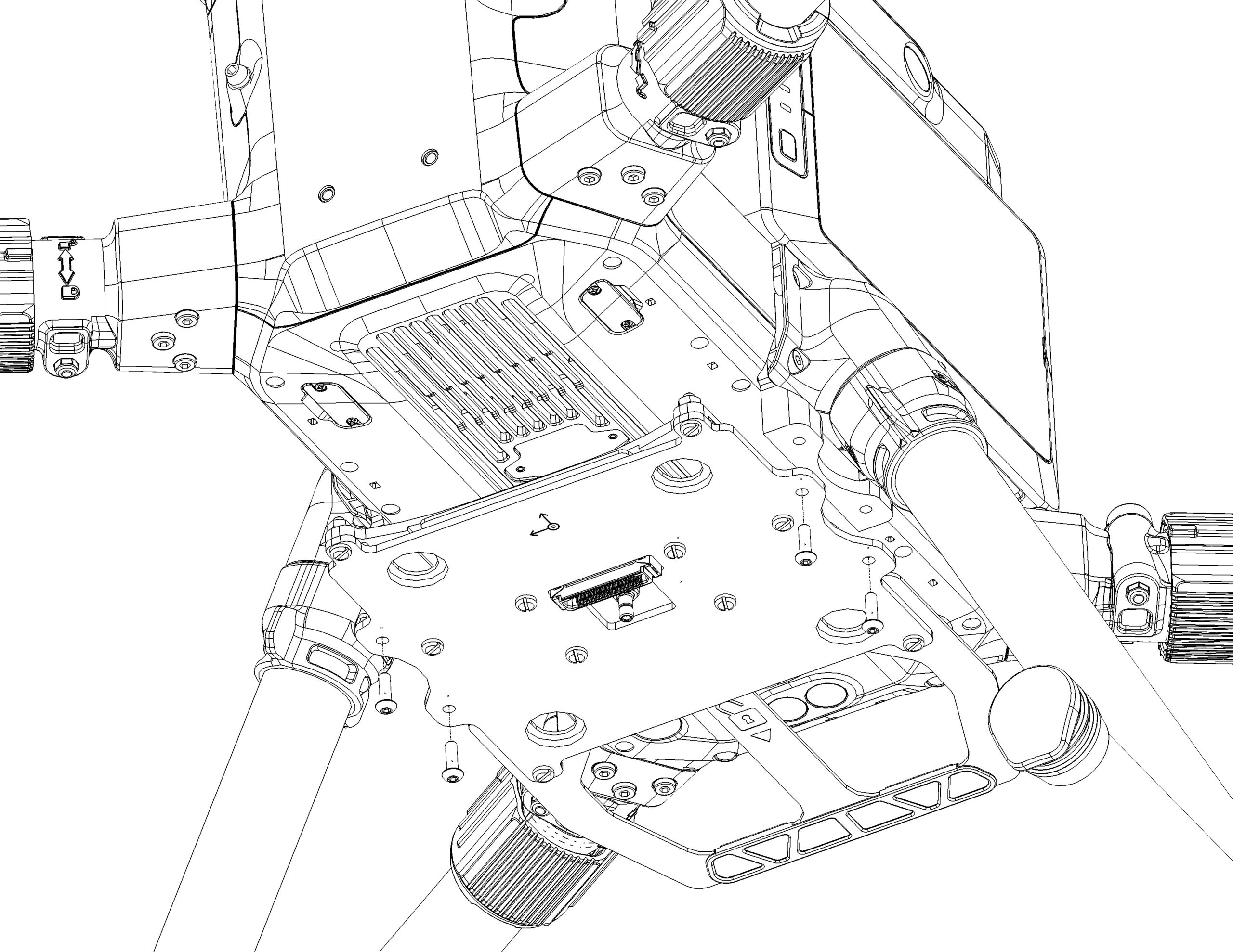
6. Be cautious of the orientation of the main plate and make sure the coordinate symbol arrow points towards to the front of the drone.

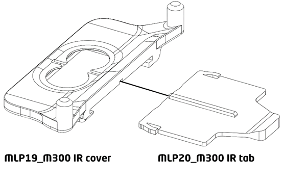
1. Assemble the IR cover by pressing in the tab into the cover until it is fully retracted. Note that the topside of the IR tab has an extrusion. Make sure the extrusion is facing the top as shown in the Figure 19 below.
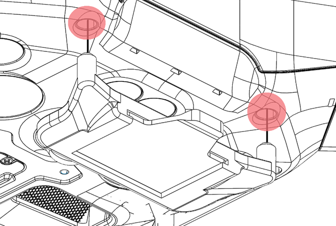
- Apply two (2) pieces of double-sided adhesive on top of the pins of the IR cover assembly.
- Mount the assembled IR cover under the base of the M300 drone by pressing the pins of the cover into the highlighted holes.
4. Make sure the IR cover is fitted tightly into the M300 drone and that all parts are fully in contact with each other.
Disable Obstacle Avoidance
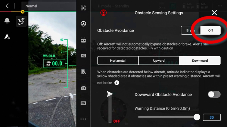
The integration of the IR Cover will cause disruption to the M300’s built-in obstacle avoidance detection systems. If these systems are not disabled, they can cause erratic and potentially dangerous behavior including loss of control of the drone. To disable obstacle avoidance, perform the following steps:
- Launch the DJI Pilot[JC3.1][JH3.2][JC3.3]2 application, open a mission, or go into manual view.
- Tap the Ellipsis menu (…) on the top right corner of the screen.
- Tap the second icon from the top Obstacle Sensing Settings.
- Tap each tab for Horizontal, Upward, and Download tap the toggle button off for each category.

M300 Carrier Case Top Foam Modification
The following steps summarize how to modify the top foam of the DJI M300 carrier case:
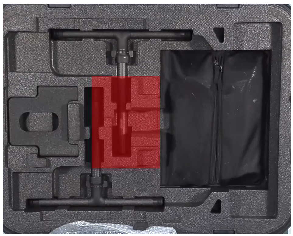
- Using a ruler and marker, trace a 180mm x 210mm rectangle starting from the top right corner of the center foam for the DJI m300 drone leg pockets as shown in Figure 2.
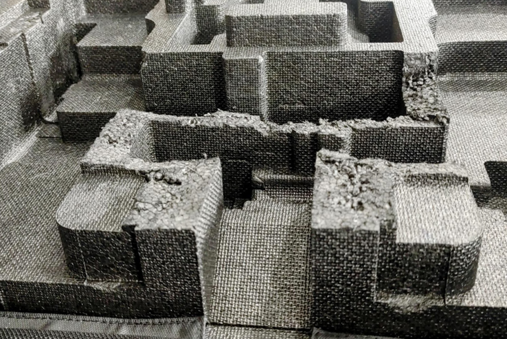
- Using a box cutter, carefully remove the marked foam from step 1 down by a depth of 15mm. Make sure to wear proper Personal Protective Equipment (PPE), (cut resistant gloves, safety glasses) before performing this step to minimize chances of injury.
M300 Carrier Case Bottom Foam Modification
The following steps summarize how to properly modify the bottom foam of the DJI M300 carrier case:
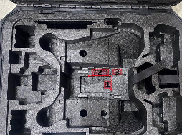
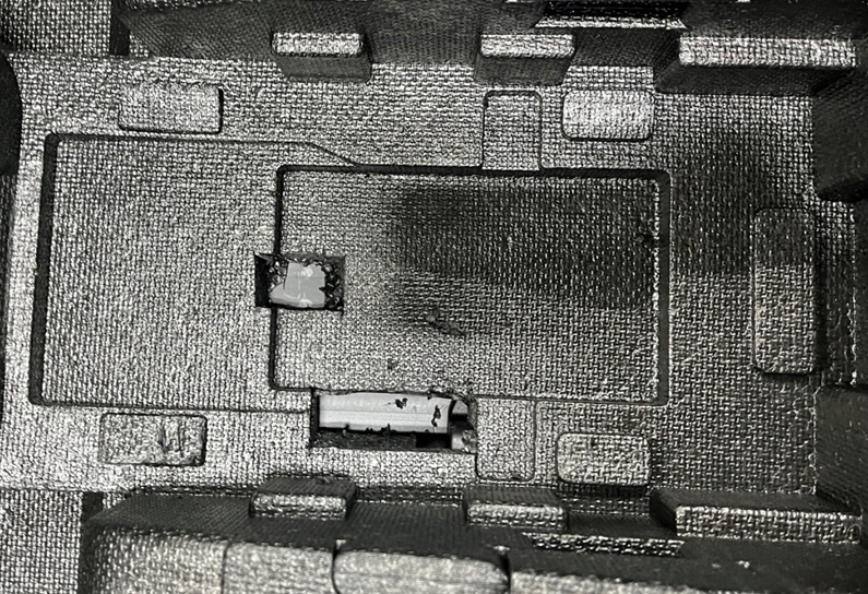
- Using a ruler and marker, trace a 17mm x 26mm rectangle starting approximately from the midpoint along the right edge of the M300’s main body pocket (i.e., deepest pocket) as shown highlighted by the number 1 in Figure 4.
- Using a ruler and marker, trace a 21mm x 58mm rectangle starting approximately 15mm from the right edge of the M300’s main body pocket (i.e., deepest pocket) as shown highlighted by the number 2 in Figure 4.
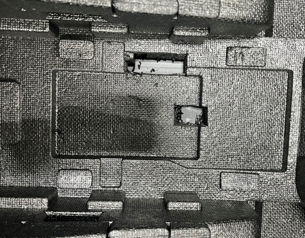
- Using a box cutter, carefully remove the marked foam from steps 1 and 2 to a depth of 26mm. There should be no remaining foam if done correctly as shown in Figure 5. Make sure to wear proper PPE (cut resistant gloves, safety glasses) before performing this step to minimize chances of injury.
- Using a box cutter, remove the top right foam bumper of the main body’s pocket highlighted by the number 3 in Figure 4.
M350 Carrier Case Top Foam Modification
The following steps summarize how to modify the top foam of the DJI M350 carrier case:
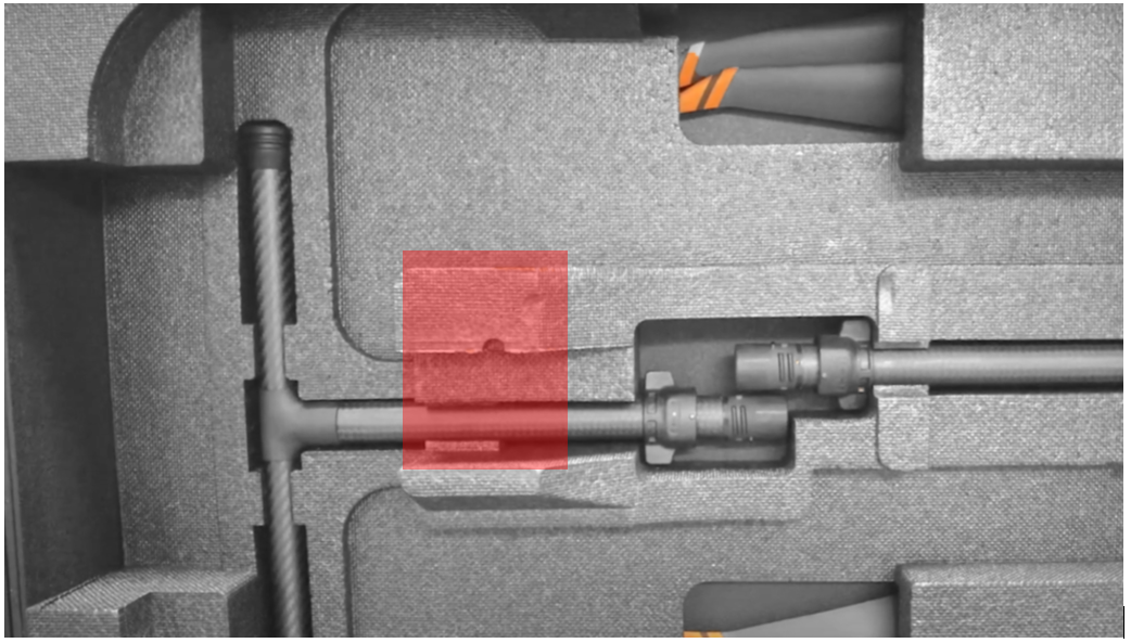
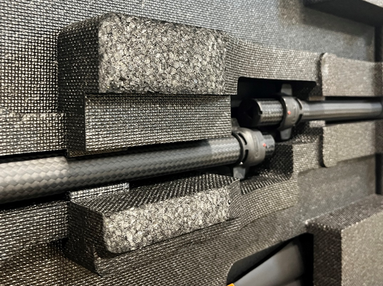
- Using a ruler and marker, trace a 180mm x 210mm rectangle starting from the top left corner of the center foam for the DJI M350 drone leg pockets as shown in Figure 6.
- Using a box cutter, carefully remove the marked foam from step 1 down by a depth of 15mm. Make sure to wear proper PPE (cut resistant gloves, safety glasses) before performing this step to minimize chances of injury.
M350 Carrier Case Bottom Foam Modification
The following steps summarize how to properly modify the bottom foam of the DJI M350 carrier case:
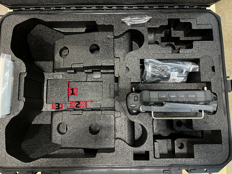
- Using a ruler and marker, trace a 17mm x 26mm rectangle starting from the midpoint along the left edge of the M300’s main body pocket (i.e., deepest pocket) as highlighted by the number 1 in Figure 8.
- Using a ruler and marker, trace a 21mm x 58mm rectangle starting approximately 15mm from the left edge and along the bottom edge of the M300’s main body pocket (i.e., deepest pocket) as highlighted by the number 2 in Figure 8.
- Using a box cutter, carefully remove the marked foam from steps 1 and 2 to a depth of 26mm. There should be no remaining foam if done correctly as shown in Figure 9. Make sure to wear proper PPE (cut resistant gloves, safety glasses) before performing this step to minimize chances of injury.
- Using a box cutter, remove the top right foam bumper of the main body’s pocket highlighted by the number 3 in Figure 8.
| Part number : MNT1002266A00T (Antenna mount included in this kit) |
Payload compatibility
The front smart dovetail adapter is compatible with all TrueView payloads equipped with smart dovetail, up to 2.7kg.
Included components
- M300 front smart dovetail adapter
- M3 x 5mm socket head screw (2)
- M3 x 20mm socket hear screw (2)
- Loctite Threadlocker Blue 243 (not pictured)
Required tools
- 2.5mm hex screwdriver
- 3.0mm hex screwdriver
Adapter Installation
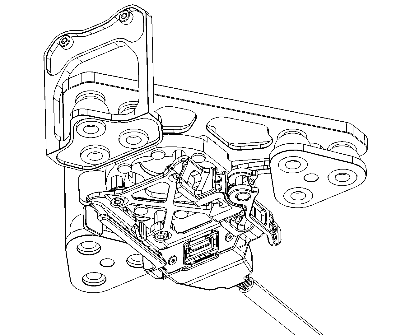
1. Removed the front DJI Skyport mount from the M300 drone.
2. Install the M300 front smart dovetail adapter using two M3 x 5mm socket head screws and two M3 x 20mm socket hear screws. Apply Loctite to all screws before installation.
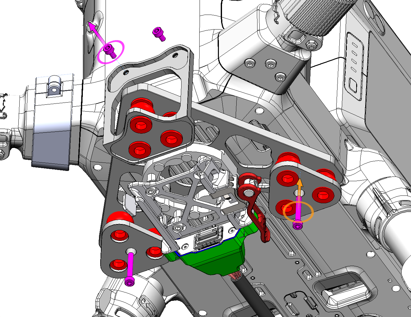
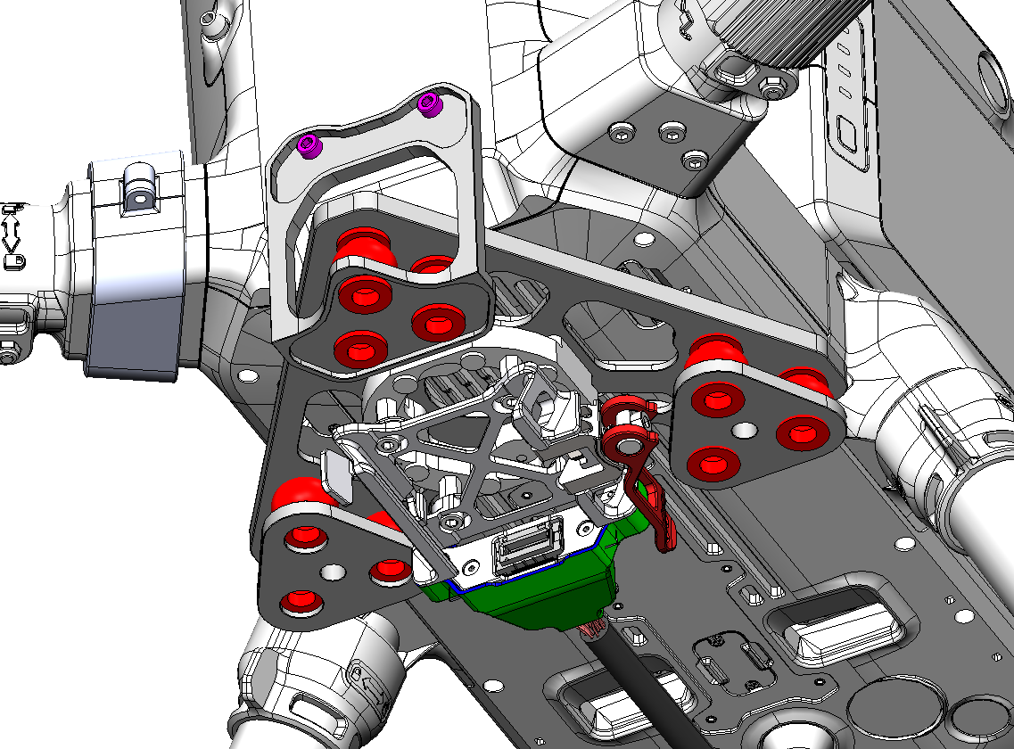
3. Connect the smart dovetail’s power cable to the drone (see section below).
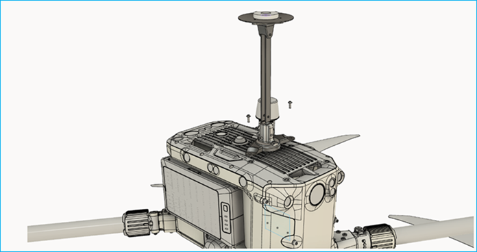
1. Insert a square piece of double-sided adhesive tape to the bottom of the Antenna Mast plus base. Make sure both sides of the adhesive have been peeled to allow for proper joint cohesion.
2. Secure the Antenna Mast plus base to the top of the DJI M300 drone using two M3x6 18-8 stainless steel button head hex drive screws and two M3 washers.
3. Attach the Antenna Mast Assembly provided inside the payload carrier case to the Antenna Mast plus base . Press the antenna mast down until the spring pin locks into the Antenna Mast.
Antenna Cable Management
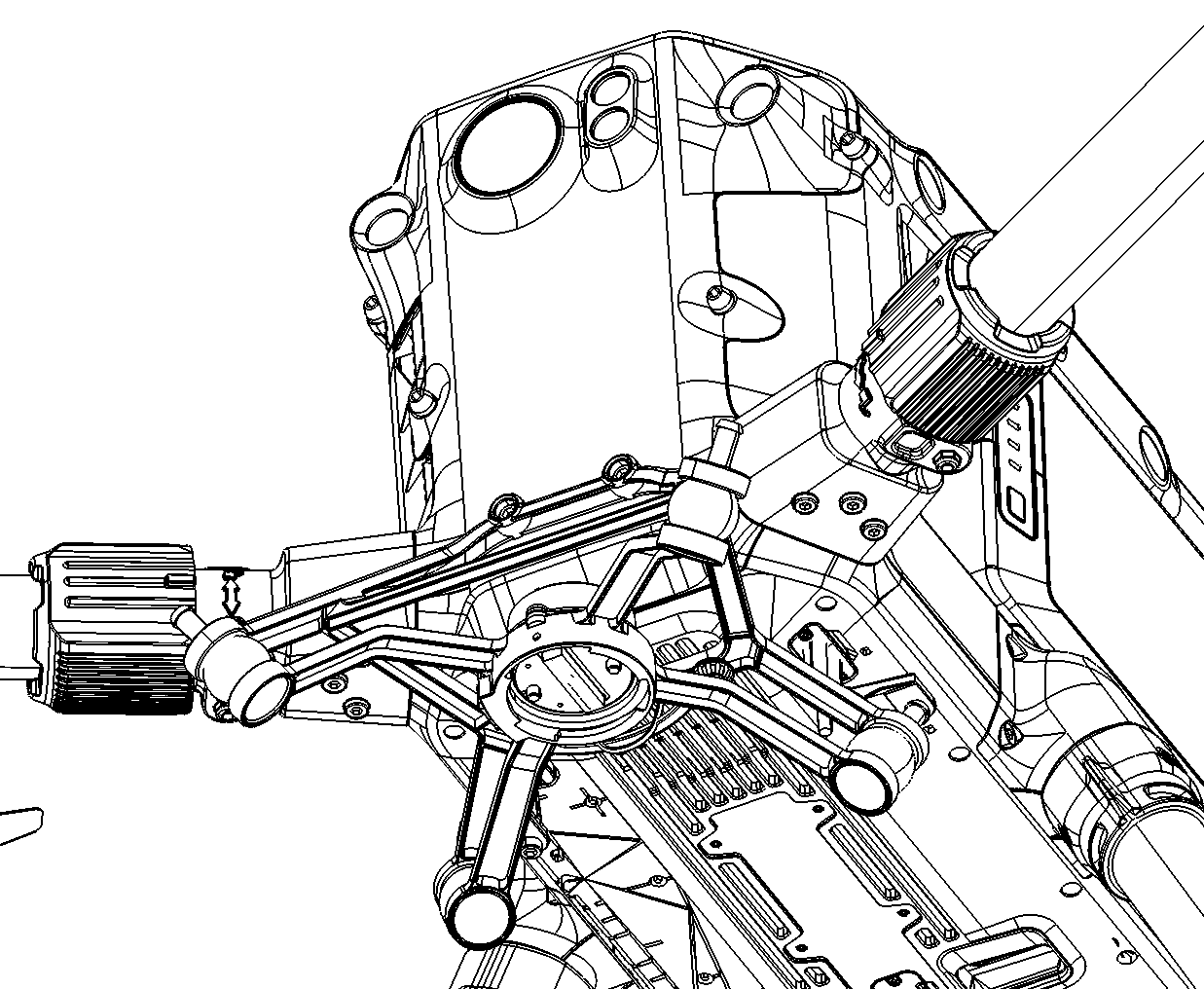
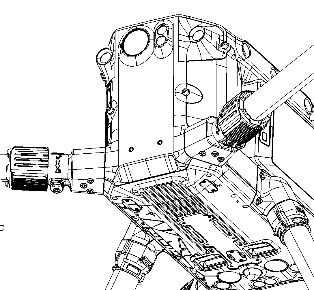
1. Install the M300 GNSS cable adapter (COA01 & COA02, ENC1001046A00T) to the front starboard motor arm using two M2.5x6mm 18-8 stainless steel socket head hex drive screws. See Figure 16 below.
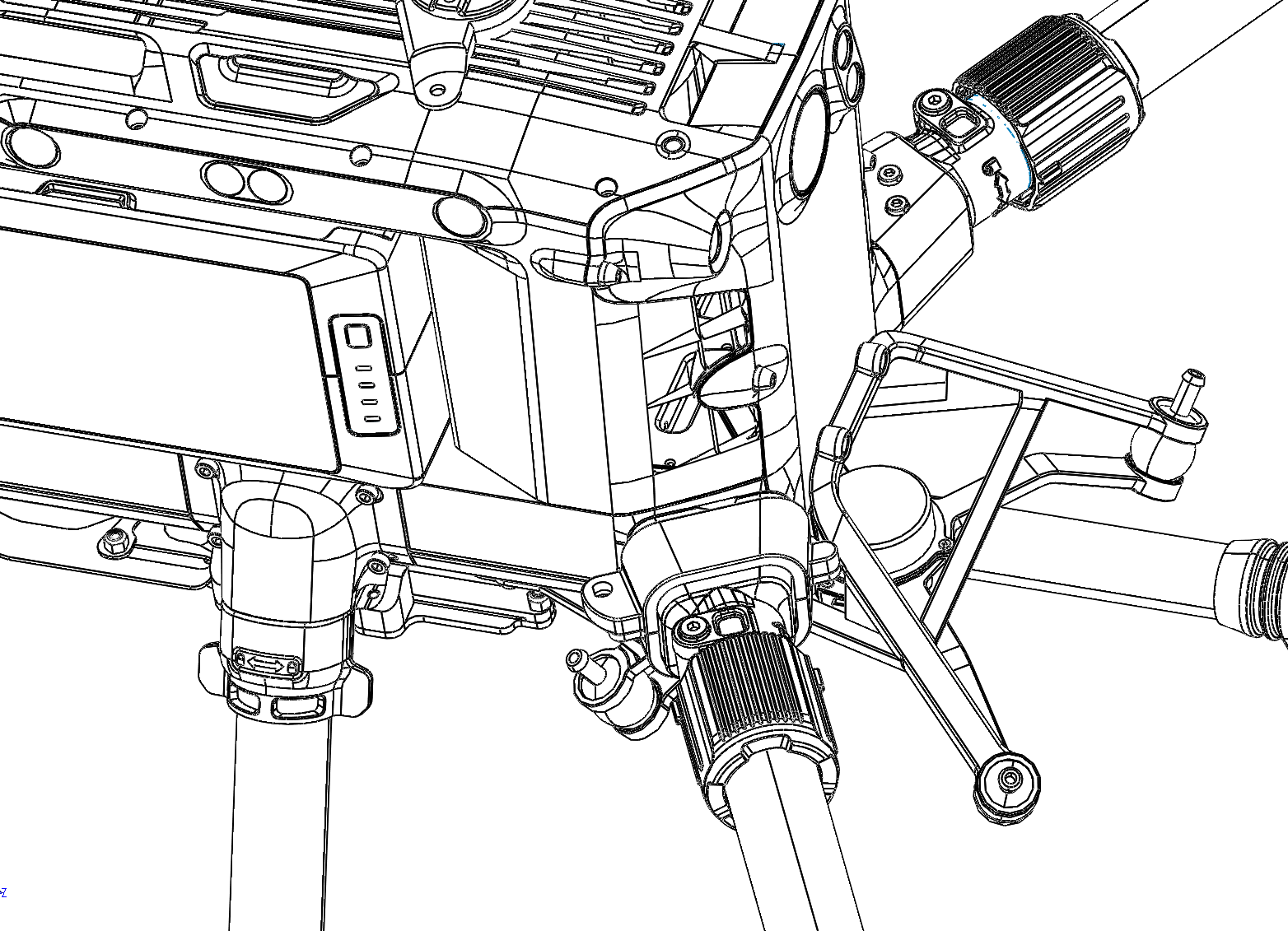
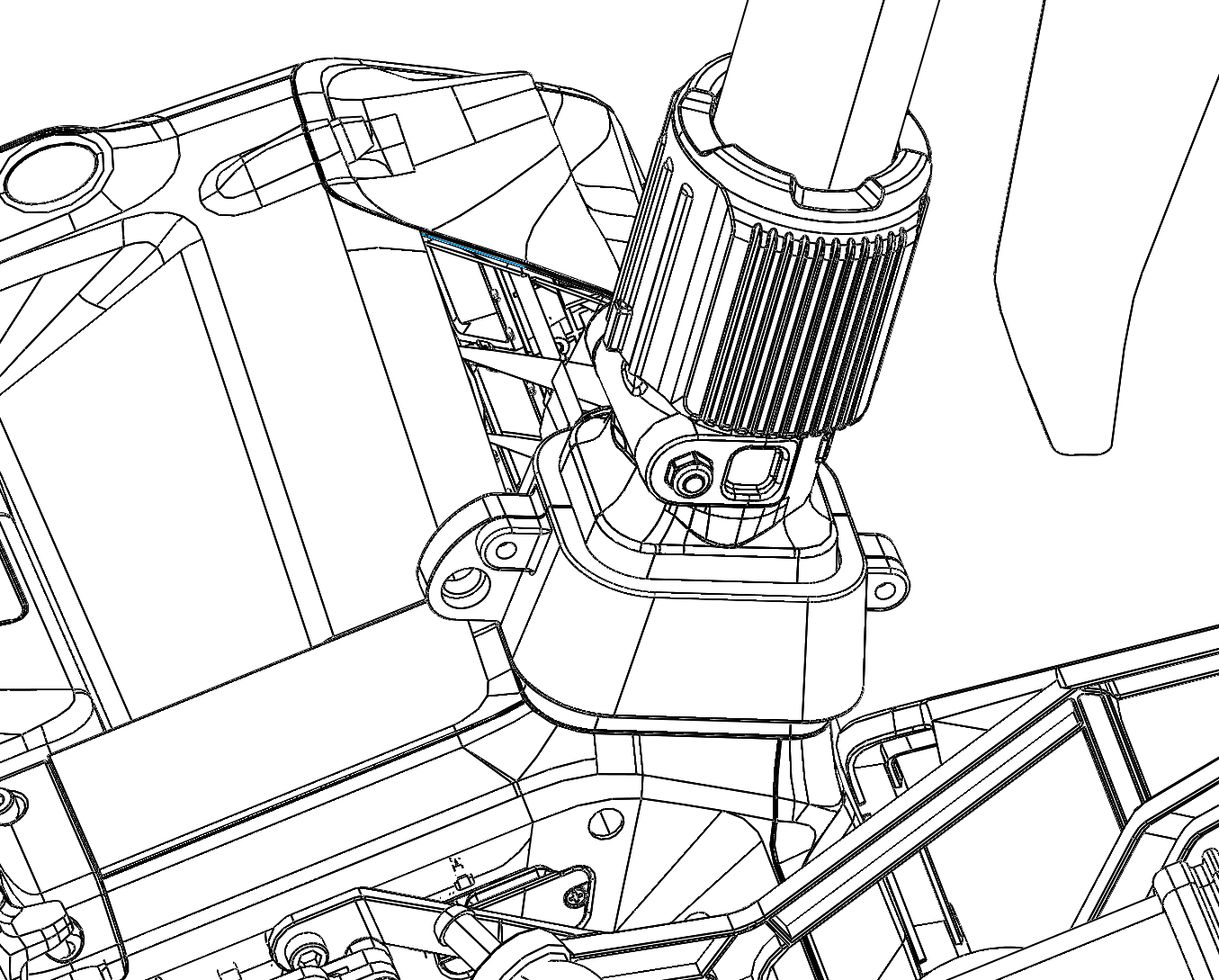
2. Pass all cabling (coaxial cable to antenna and power cable for payload) along the starboard side of the drone.
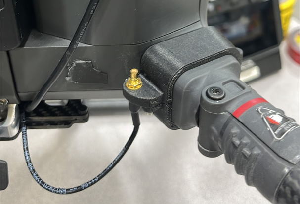
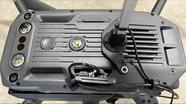
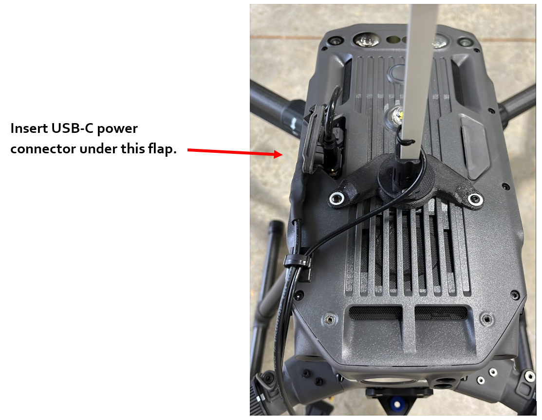
a. The coaxial cable goes to the GNSS adapter. A secondary cable connects from the GNSS adapter to the antenna mount. Use a cable clip on the top of the drone to reduce cable movement during operation as shown in Figure 17.
b. The power cable goes to the USB-C connector on the top of the drone on the starboard side. Use a cable clip on the top of the drone to reduce cable movement during operation as shown in Figure 17.
Payload-specific integration
The TrueView 539/540 series payloads come with a Skyport-compatible adapter to mount on the M300/M350.
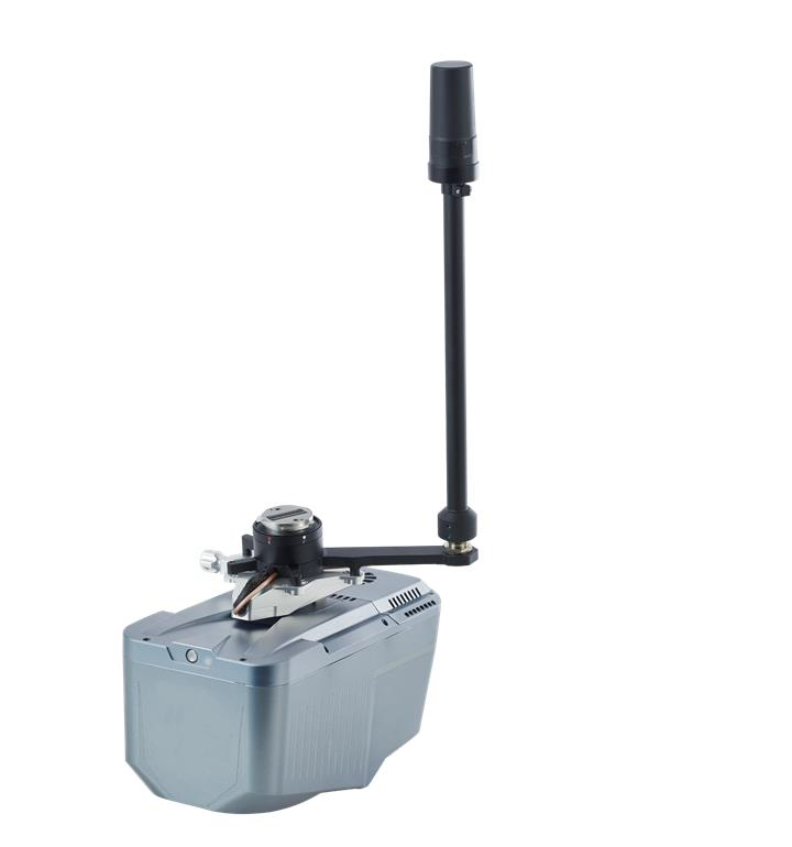
| Part number : MNT1002113A00T (Antenna mount included in this kit) |
Replace M300 Shock Absorbing Balls
Since the maximum load weight of the original shock-absorbing ball of the M300 is less than 1Kg, it is necessary to replace the original shock-absorbing ball to the new equipped balls.
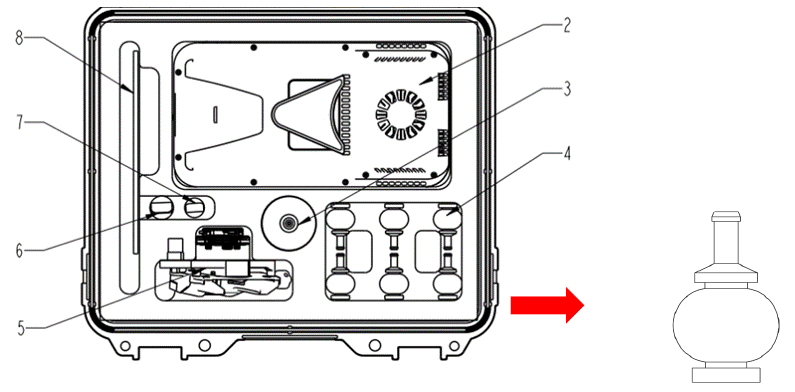
1. Take out the shock-absorbing balls from the transport container (slot 4).
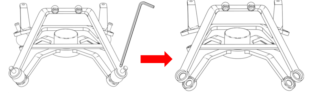
2. As shown in the following figure, remove 4 original shock-absorbing balls from M300 using M4 allen wrench (it is recommended to replace all the original shock-absorbing balls one by one). Push the shock-absorbing ball from the groove edge towards the center. Repeat this process a few times until it comes off. Avoid pulling or yanking with force, as it may cause damage to the shock-absorbing ball.
When removing the shock-absorbing ball, use the round end “1” to remove it. Do not use the right-angle end “2” to remove it, as it may damage the shock-absorbing balls.

3. Replace all the original shock-absorbing balls one by one. When installing the new shock-absorbing ball, insert the bottom rubber ring down first, then insert the top rubber column from the top bracket and pull the rubber column up.
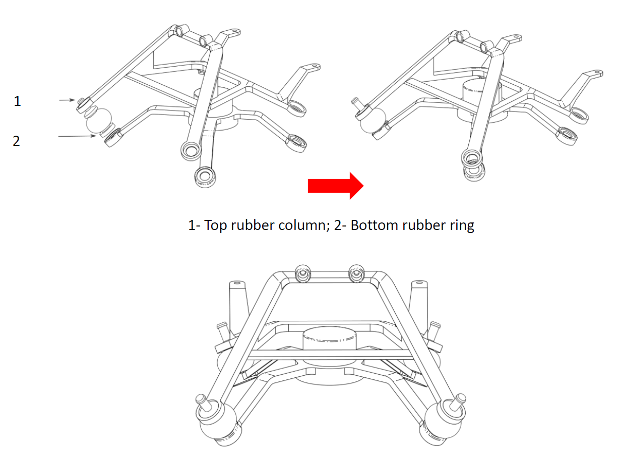
It is recommended to install a new shock-absorbing ball every time when user remove an original one to prevent the load plate from falling off or becoming misaligned.
M300 Installation Steps
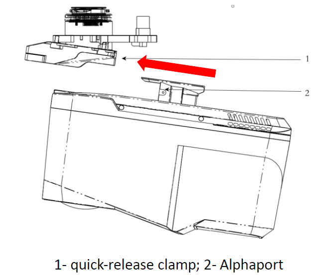
Push the “Alphaport” slider of scanner into the quick-release clamp which on the bottom of the airborne mounting platform in the direction of the arrow until hear a “click” sound.
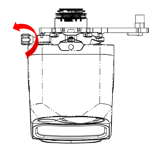
Tighten the side screw bolts to make it stable and finally finished the installation.
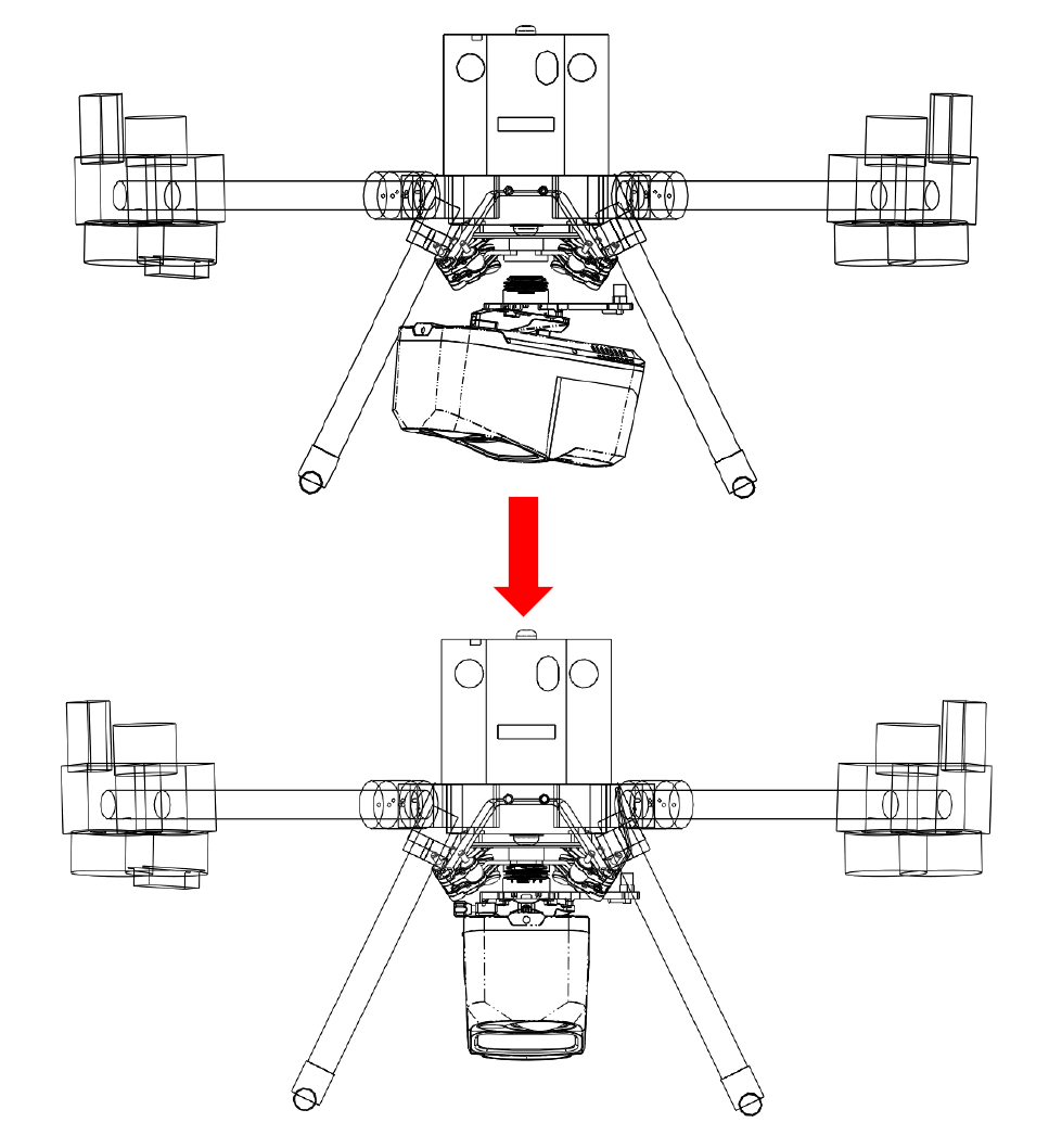
Align the white dot on the device Skyport interface with the red dot on the M300 interface and embed it in the installation location. Rotate the device SkyPort interface to the locked position (red dots align red dots) to be fixed.
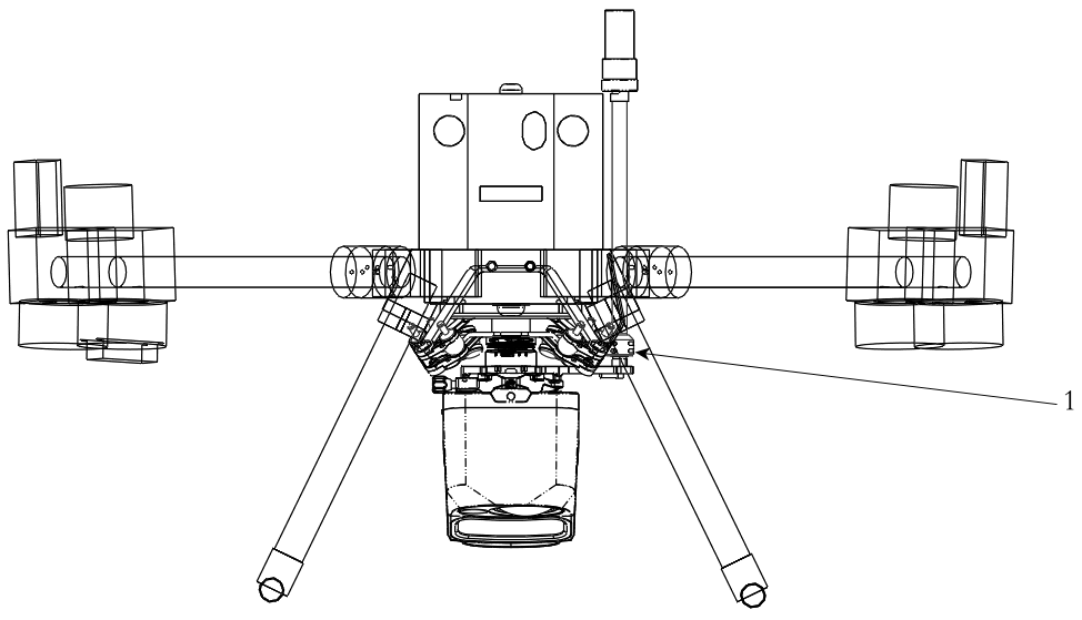
Insert the rod antenna into the antenna mount and tighten it.
References & Printable versions
Printable versions of this guide are available as PDF documents.
PLI Guide
Payload Profiles
For information on payload lever arms and profiles, please consult the following article :
Support
For troubleshooting how to mount your TrueView on an M300/M350, error messages, or additional workflow information, please Contact Support for assistance. Include your contact info, company name, product/version, and model/serial number for faster service.
