Introduction
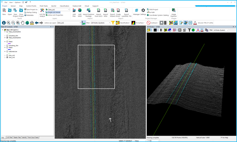
Three-dimensional point clouds of railways can be used to examine potential hazards along the railway infrastructure, identify track distortions and areas in need of maintenance. LP360 Drone includes tools to automatically extract a rail alignment (centerline) feature as a polyline as well as classify “top of rail” from LAS files derived from Laser Intensity Detection and Ranging (LIDAR) points. This feature is implemented as a semi-automated Point Cloud Task (PCT). For the best performance of the Rail Extraction PCT, you will need to run the tool on the raw LAS data. A smoothed dataset will cause the data to lose the shape of the rails in the point cloud and make it more difficult to classify using the PCT. For a video walkthrough using the Rail Extractor, please see the How to Extract Rail Tracks with LP360 Drone page.
Using Rail Extractor
Before executing the tool, it is helpful to create a new feature at the start of your rail centerline using the Create Feature tool on the Feature Edit ribbon. This ensures that, with each execution of the tool, the centerline is started in the exact same location. This feature layer can then be used to execute the PCT (By Feature Layer![]() on the Point Tasks Ribbon). The tool can also be executed using the By Line
on the Point Tasks Ribbon). The tool can also be executed using the By Line ![]() option on the Point Tasks Ribbon.
option on the Point Tasks Ribbon.
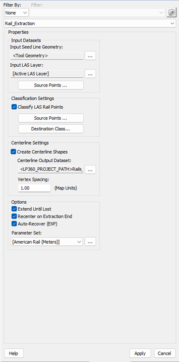
To the left is a screenshot of the Rail Extraction point cloud task in LP360. As you can see, there are a number of input options available. This tool can generate a centerline of the detected rails and classify out the rail points with the option to Extend Until Lost, meaning the algorithm will search for rails until it can no longer detect any candidate points.
There is also an option to change the Parameter Set which is specific to the type of rail road being extracted. The Rail Extractor tool comes with two default Parameter Sets: American Rail (Meters) and American Rail (Feet). These two default Parameter Sets have preset values that are derived from the American Railway measurements.
In this example, the [American Rail (Meters)] parameter set is selected. Click the ellipse (…) button next to the [American Rail (meters)] drop down to open the Parameter Set dialog in order to edit or create a new parameter set.
Rail Extraction Parameter Set Manager
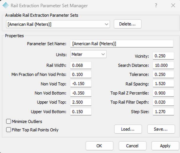
There are 13 unique parameters for the Rail Extraction Parameter Sets that allow for processing and classification of different rail ways around the world. There are 4 parameters that are directly derived from the specific, physical rail road measures. The Rail Width, Rail Spacing, Non-Void Top, and Upper Void Bottom parameters are pre-determined based on the specific railway you are looking to classify. The Rail Width refers to the physical width of the rails themselves. The Rail Spacing is the distance from rail center to rail center. The Upper Void Bottom and Non-void Top are inverted measures of the height of the rail.
Important things to consider for this tool are the use of Void and Non-Void space. These “spaces” allow the algorithm to determine a relative elevation range that the rails themselves would be found and eliminate candidate points that may have obstacles or points in the areas that should be void of all objects (the area in which the rail cars would travel).
To the right is the Rail Extraction Parameter Set Manager. There are several parameters that can be edited, however certain values come directly from the physical rail road measures. When setting custom parameters, the Parameter Set Name can be chosen. After editing the parameters (and entering a unique name) click apply, and the setting will be saved as a drop-down option to use with future projects.
Parameter Set Descriptions
- Rail Width – defines the width of the physical rail. Specific measures can be located on the Wiki Standard-Gauge Railway webpage.
- Min Fraction of Non-void Points – Numerical value between 0 and 1 specifying the fraction of LAS Points in the vicinity of the LAS point under consideration that must fall into the Non-void elevation range for the LAS point to be considered a rail point
- Non-Void Top – Numerical value between Non-void Bottom and Upper Void bottom specifically the upper bound of an elevation range in which some vicinity LAS points must exist for a LAS point to be considered a rail point. This parameter is RELATIVE to the elevation of the LAS point under consideration.
- Non-Void Bottom – Numerical value between negative infinity and Non-void Top specifying the lower bound of an elevation range in which some vicinity LAS points must exist for a LAS point to be considered a rail point. This parameter is RELATIVE to the elevation of the LAS point under consideration.
- Upper Void Top – Numerical value between Upper Void Bottom and infinity specifying the upper bound of an elevation range in which no vicinity LAS points can exist for a LAS point to be considered a rail point. This parameter is RELATIVE to the elevation of the LAS point under consideration.
- Upper Void Bottom – Numerical value between non void top and upper void top specifying the lower bound of an elevation range in which no vicinity LAS points can exist for a LAS point to be considered a rail point. This parameter is RELATIVE to the elevation of the LAS point under consideration.
- Vicinity – Numerical value between 0 and infinity specifying the radius of a circle centered about the LAS point under consideration when applying elevation pattern criteria.
- Search Distance – For direction alignment type only. Numerical value between 0 and infinity specifying how far away in perpendicular distance from the alignment to search for rail points.
- Tolerance – Numerical value between 0 and Rail Spacing/2 specifying the allowable deviation from Rail Spacing for LAS points to be considered opposing rail points.
- Rail Spacing – Numerical value between 0 and infinity specifying the nominal rail spacing (gauge)
- Top Rail Z Percentile – Numerical value between 0 and 1 specifying the percentage of rail points within a step (defined by Step Size) that must have a lower elevation value than the point which is considered to be at the top of the rail.
- Top Rail Filter Depth – Numerical value between 0 and infinity specifying the elevation range centered on top of rail geometry that is used when classifying Top Rail Points Only.
- Step Size – Numerical value between 2*Tolerance and Rail Spacing-Tolerance, specifying the length of the sample along the alignment used to compute a rail XYZ coordinate.
For general context on what each of these values represent in relation to the railway itself, please see the figures below.
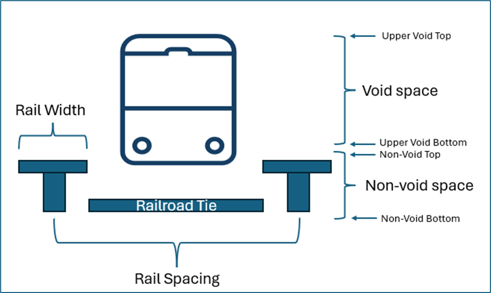
The Void Space (bound by the Upper Void Top and Upper Void Bottom parameters) is the relative space above the rails that shouldn’t be occupied by any objects (therefore no points) as this is the space a rail car would travel. This space is important in removing candidate points that have points (objects) above them that would not allow for a rail car to travel. The Non-Void Space (bound by the Non-Void Top and Non-Void Bottom parameters) is the relative space in which the rails themselves reside.
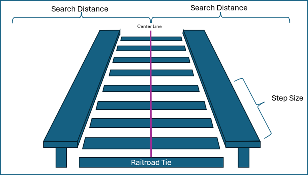
The Search Distance is the distance from the centerline that the algorithm can search for candidate points to be considered part of a rail. The Step Size is the width (or depth) of the window for each search.
