1. Introduction
This article is meant to give recommendations for a corridor mapping project with UAV. Corridor mapping refers to the process of capturing detailed spatial data along a linear path such as a road, railway, or powerline. These missions typically involve long flights with relatively few flight lines and present unique challenges.
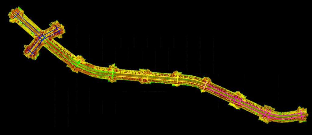
Example of a corridor mapping project:

Out of all aerial mapping configurations, corridor mapping is the most demanding on the IMU. The IMU is essential for accurately positioning the LiDAR data in space, and any errors due to drift will directly impact the quality of the final dataset.
The IMU drift can reduce the quality of the trajectory, which will be seen as misalignments between flight lines. Good planning will minimize these effects, and if they occur, the user will have the tools to fix them.
2. Planning recommendations
These recommendations focus on reducing IMU drift and detecting it if it occurs. Remember that the IMU drift happens when the IMU is heading in the same direction for a long time. The time depends on the IMU quality, it is not the same to work with a high-end IMU like the Applanix APX-20, than with an entry-level like the DJI L2.
2.1. One battery per flight
Plan each flight segment (or block) to last no longer than a single battery cycle. This way all blocks will include all the recommended features, and can be processed individually. In the same way, if a block has an issue, it will be possible to use adjacent blocks to fix it.
2.2. Two parallel flight lines
Never plan a corridor mission with just one flight line. Two or more parallel lines (i.e., out-and-back paths) ensure that any misalignment becomes easier to detect and correct during processing.
2.3. Perpendicular flight lines at the beginning and end
These cross lines should intersect all parallel flight lines, used to verify the alignment of multiple flight lines. Since there will be 3 flight lines, the user should be able to detect which flight line is misaligned. Remember, if you only have 2 flight lines, and they do not align, it is impossible to detect which is the problematic flight line. It will also

2.4. Plan overlap area in multi-fight project
When your corridor extends beyond a single battery’s capacity and requires multiple flights, ensure that each flight overlaps the next. This overlap area is critical for the alignment of multiple flights.
2.5. Avoid long straight lines
Straight flight lines extending beyond 300 seconds increase the chance of IMU drift. If your corridor is totally straight, artificially introduce a directional change mid-way to avoid the IMU drift.
A good practice is to insert a short perpendicular flight line, for example, every 300 seconds, especially in very straight corridors.
Two examples of mid-way directional change:
Black –> Flight lines
Yellow –> Mid-way directional change
2.6. Place properly the GCPs
The best places to set up ground control points or check points are:
- At the start and end of each flight block.
- In each overlap area between flights.
- Every 500 meters along the corridor.

If plan properly, the start and end GCP will also cover the overlap area in contiguous flights.
