Some scenarios may require you to process your TrueView 3DIS data with different lever arm offsets, IMU mounting angles, or Vehicle to reference angles than the ones recorded in the APX at the time of acquisition. For instance, if you move the system to a new drone, but forget to update the lever arm values following the applicable system hardware users guide before collecting data. The steps below explain how to use a lever arm offset override to process your data in LP360 Drone, formerly TrueView EVO, with different lever arm offsets. Applies to LP360 Drone and TrueView EVO v2021.1.17.0 and later.
Step 1 – Import your cycle into LP360 Drone.
Step 2 – In Windows File Explorer, navigate to the system folder inside your project folder (Project\Area\Cycle\System), or a folder of your choosing.
Step 3 – Create a json file named GNSSLeverArmOverride.json that defines one or more of these 3-tuples to define the lever arm offset override:
{
 "IMUMountingAngles": {
 "Override": "false",
 "RefToIMUMountingAnglX": "0.0",
 "RefToIMUMountingAnglY": "0.0",
 "RefToIMUMountingAnglZ": "0.0"
 },
 "LeverArm": {
 "Override": "false",
 "PriGNSSLeverX": "0.0",
 "PriGNSSLeverY": "0.0",
 "PriGNSSLeverZ": "0.0"
  },
 "VehicleToRef": {
 "Override": "false",
 "VehicleToRefAnglX": "0.0",
 "VehicleToRefAnglY": "0.0",
 "VehicleToRefAnglZ": "0.0"
 }
}
Or, use these 3-tuples for the TrueView 620, 640, 660, 680 or 720:
{
 "IMUMountingAngles": {
 "Override": "false",
 "RefToRemoteIMUMountingAnglX": "0.0",
 "RefToRemoteIMUMountingAnglY": "0.0",
 "RefToRemoteIMUMountingAnglZ": "0.0"
 },
 "LeverArm": {
 "Override": "false",
 "PriGNSSLeverX": "0.0",
 "PriGNSSLeverY": "0.0",
 "PriGNSSLeverZ": "0.0"
  },
 "VehicleToRef": {
 "Override": "false",
 "VehicleToRefAnglX": "0.0",
 "VehicleToRefAnglY": "0.0",
 "VehicleToRefAnglZ": "0.0"
 }
}
Being sure to set the override to “true” for the desired section(s).
Step 4 – Enter the desired lever arm offsets and/or mounting angles. Save and close the GNSSLeverArmOverride.json file.
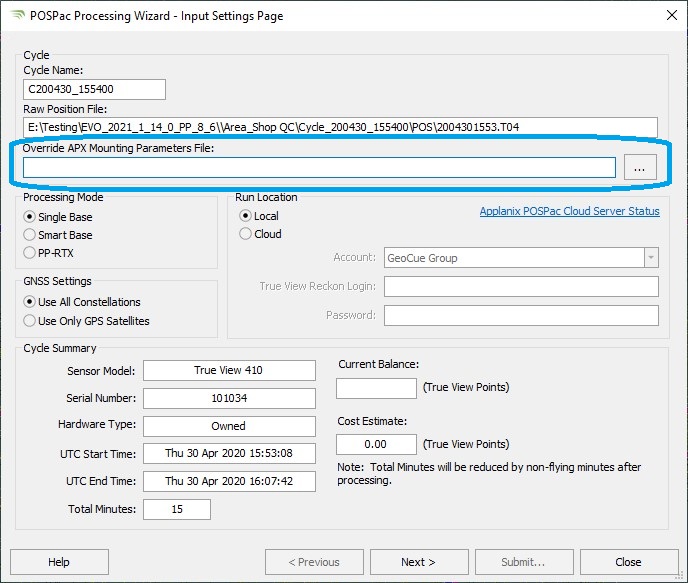
Step 5 – In LP360 Drone, select the sensor Trajectory Processing on the Sensor tab to start the POSPac Processing Wizard. On the Input Settings Page, browse to a JSON file that defines one or more of the 3-tuples above to override the APX values when processing. Configure the remaining as normal.

Step 6 – Confirm the correct offsets were used by examining the GNSS-Inertial Processor Configuration section of POSPac report.

Step 7 – Execute the remaining processing steps as normal. Be sure to re-create the TrueView Trajectories and subsequent steps if they were previously created with incorrect lever arms used in the POSPac processing.