1. Introduction
In this article we will explain step by step how to process a TV540 dataset in LP360 Drone. The idea of the article is to serve as a quick user guide on processing. This article will not explain in detail each of the settings available in each step, that can be found either in the help section or in the LP360 Drone User guide.
2. Import
1- Open LP360 v2024.2.13 or newer
2- Select “Import Raw Missions into New Project…”
3- Select “TrueView / Microdrones”
4- Press “Folder” to import the raw data from the sensor. You can select 1 or more cycles (flights) to be process in the same project.
Note: the very first time you select TV540 data the software will ask you to install the LP360 sensor extension.
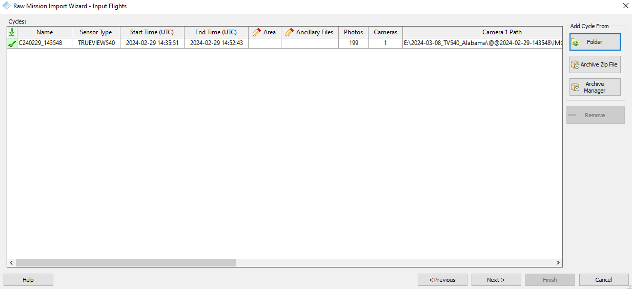
Tip: Remember that the data needs to be downloaded first from the sensor using TV540 data copy tool.
5- Press Next
6- Select the base station file in Rinex format –> Next
7- Select the Project Root Folder and the Project Name
8- Select the desired CRS
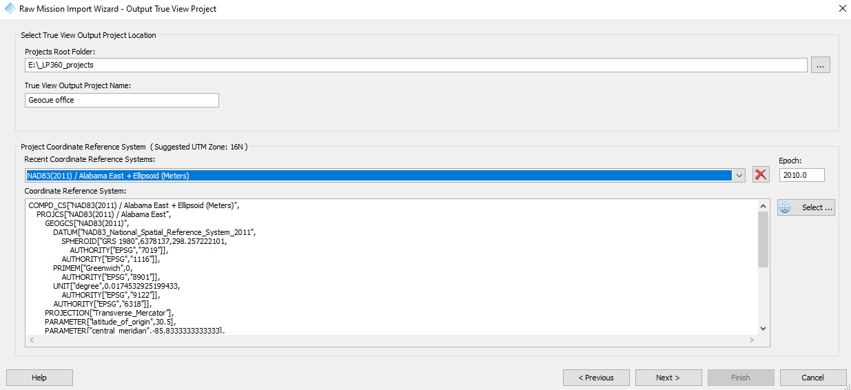
Tip: If you do not know the CRS, you can always select WGS84 UTM zone XX in Ellipsoidal heigh. LP360 shows the recommended UTM zone.
9- Press Next –> The summary will be display –> Press next
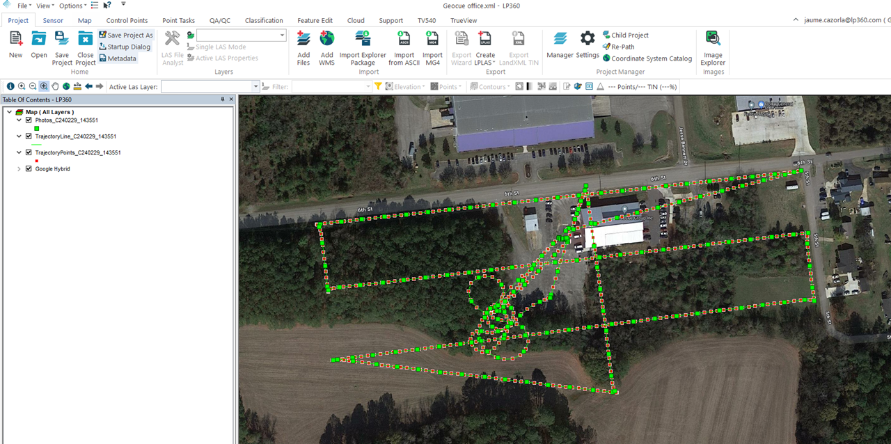
10- Data imported
3. Point Cloud generation
3.1. Trajectory Processing
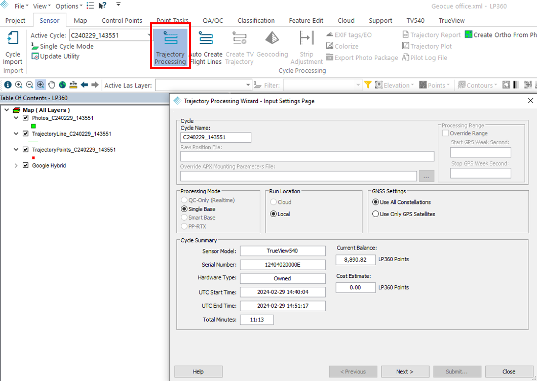
1- Go to “Sensor” ribbon–> Trajectory Processing –> Next
2- In the base station section –> Press “Survey Nail” –> Press “Add”
3- Add the base station coordinates (latitude, longitude, heigh in meters and datum) –> Press “OK” –> Press “OK”
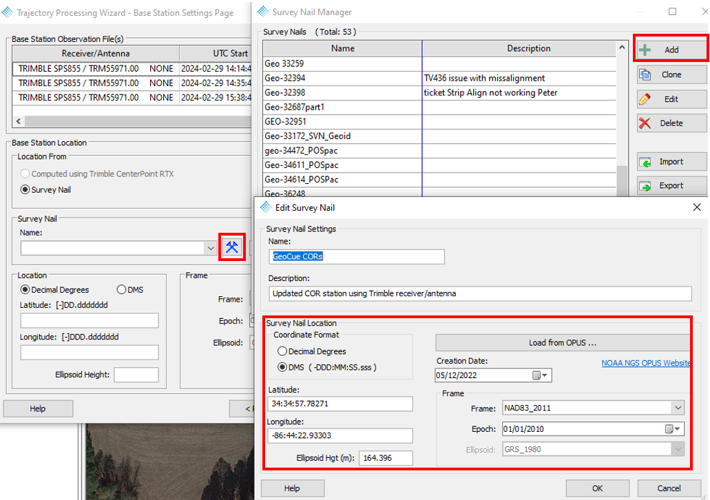
4- Review the Antenna Height and the APC Offset
Tip: If the “APC Offset” is in red means that LP360 was not able to identify the offset of the antenna. Then add manually the value. If you do not know the offset value, you can get it at NOAA antenna calibration.
5- Press “Next”
6- Review the Trajectory Processing summary –> Press “Submit” –> A confirmation window will appear, press “Continue”
7- Go to “Job manager” to monitor the processing status
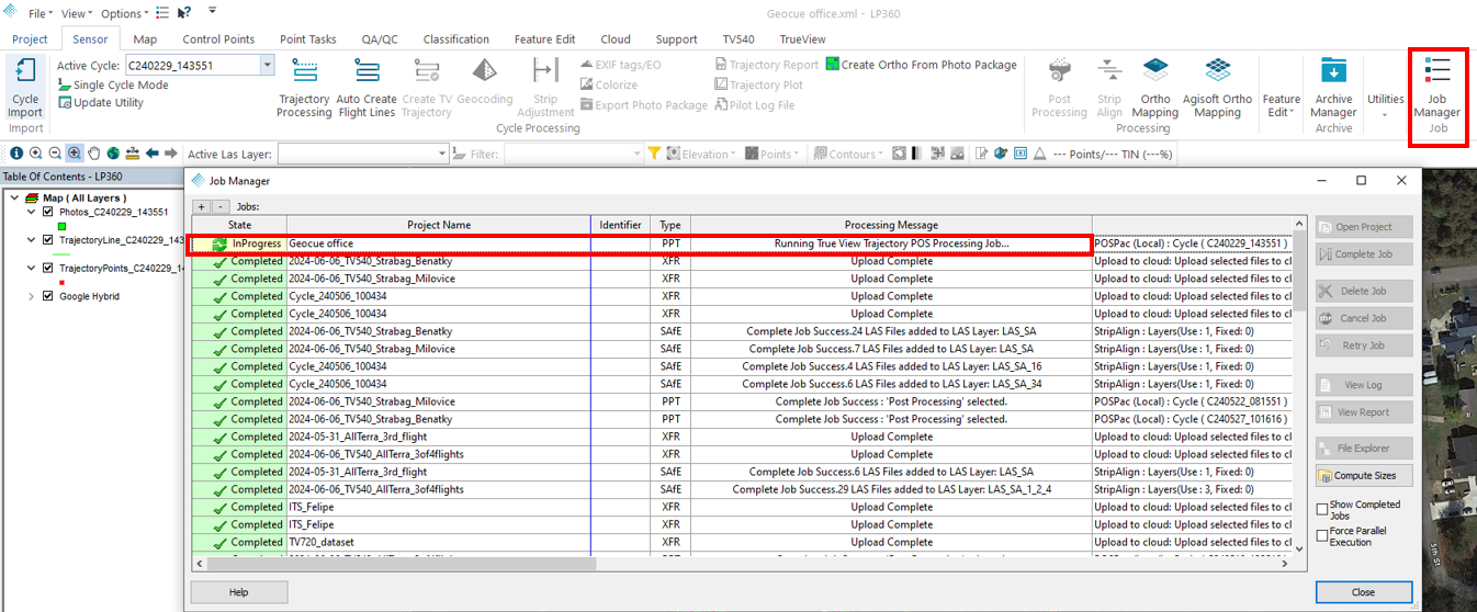
8- Once the job is completed, it will appear as “Ready” in the “Job manager” –> Select it–> Press “Complete Job”
3.2. Flight lines generation
1- Go to Sensor ribbon
2- Auto Create Flight lines –> Compute Flight lines
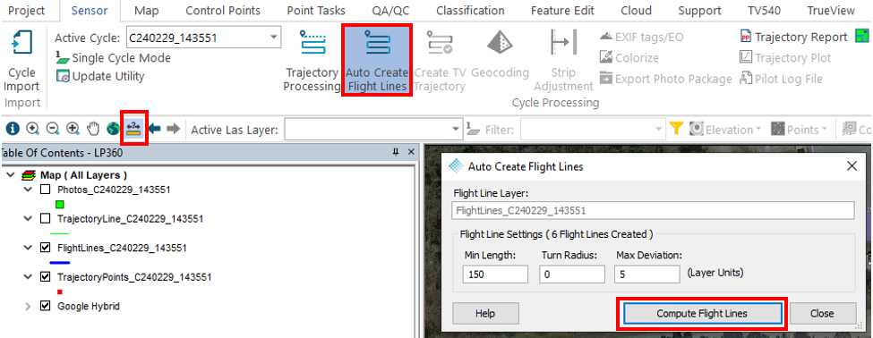
Tip:
– Use the “Measure” tool to learn approximately the flight line length.
– Make the “Min. Length” smaller than the smallest flight line.
– Make “Max. Deviation” bigger if terrain following is used. The example is in feet.
4- Select the undesired flight lines and delete them.
5- Feature Edit –>Select –> Click on the flight lines –> Press “delete” in your keyboard
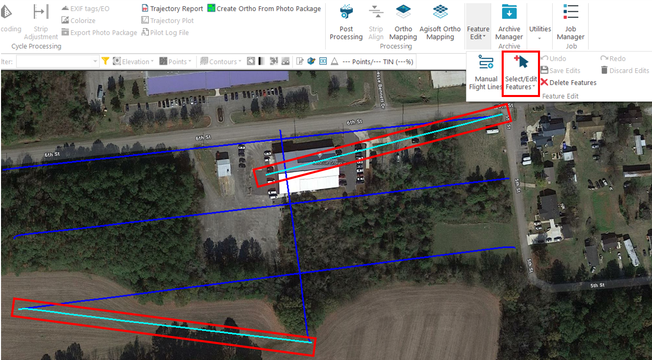
Tip: It is possible to create manual flight lines.
3.3. Post Processing point cloud
1- Go to Sensor ribbon –> Post Processing tool
2- Select the Clip Angle
Tip: clip angles is 50% of the FOV, if we select 37 deg clip angle means 74 deg FOV. The maximum TV540 LiDAR FOV is 75 degrees. I recommend using the maximum FOV with the TV540.
3- Select the Clip Range
Tip: If you want to generate all the points with no filter, uncheck “Clip Angle” and “Clip Range”.
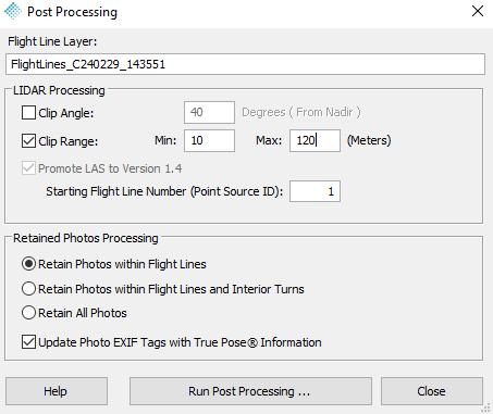
4- Run Post Processing …
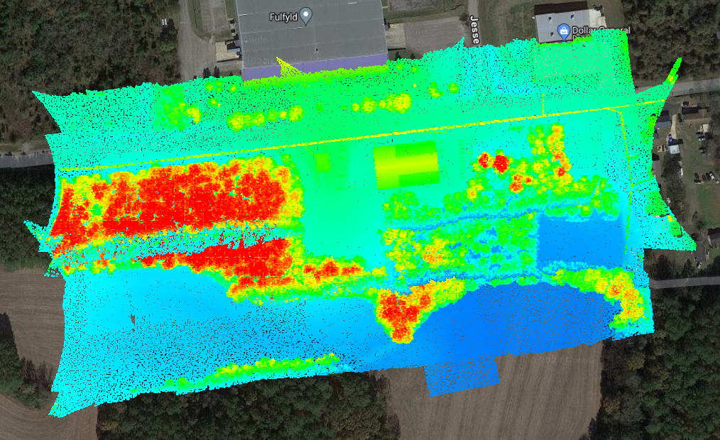
Post processing will generate a the point cloud divided by flight lines.
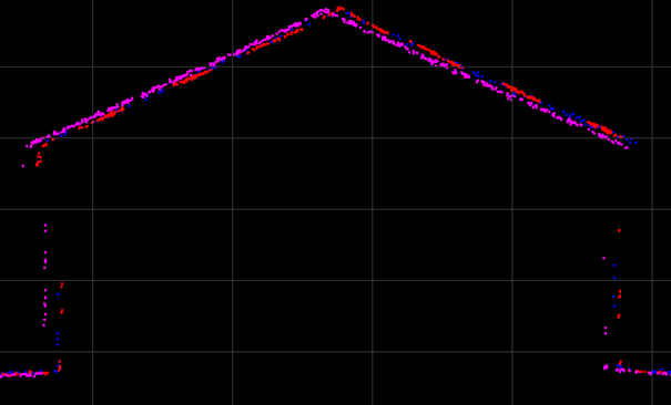
4. Strip Align
The next step will be to verify the alignment of the flight lines and correct it. For that we should perform cross sections in the overlap areas between flight lines. It is recommended to perform this sections in flat areas, buildings are especially useful for it.
We can also use tools like “Surface Precision” to verify the alignment across the flight or between multiple flights. After we have verify the alignment, we proceed to correct it.
Strip Align tool requires the license addon “Strip Align“
1- Go to Sensor ribbon –> Strip Align
2- Select the LAS to align.
Tip: You can select multiple flights. If you do it, the tool will correct any misalignment between flights. However, if one flight has significant error (or bias), it will introduce error into the new Strip Align layer.
3- Press “Submit Strip Align job”
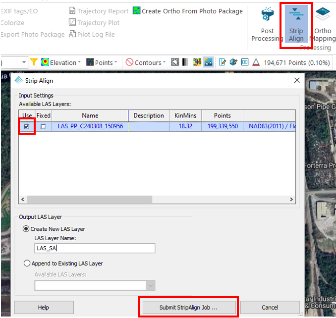
4- Go to “Job manager” –> Check the processing status
5- Once Strip Align finish the status will change to “Ready” –> Select the job–> Click “Complete job”
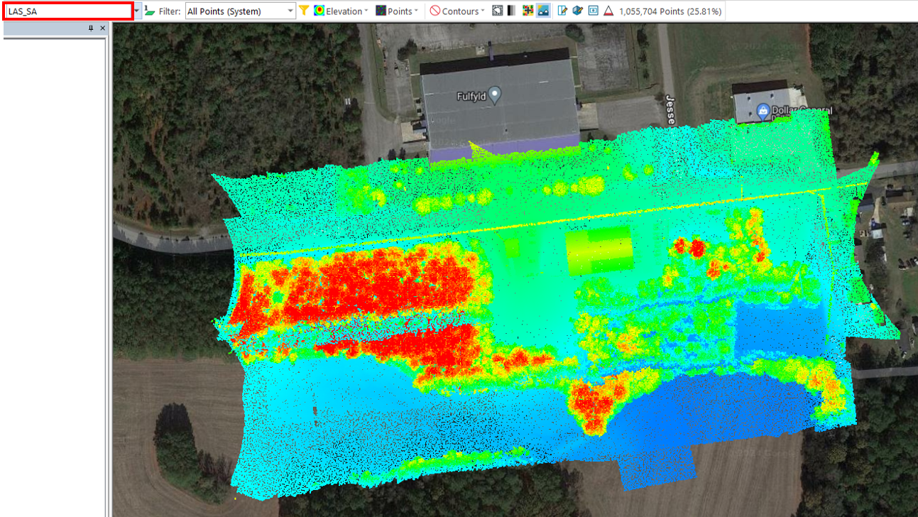
Strip Align will create a new LAS, in my case it is called “LAS_SA”. This new LAS has all the misalignments corrected. Example:
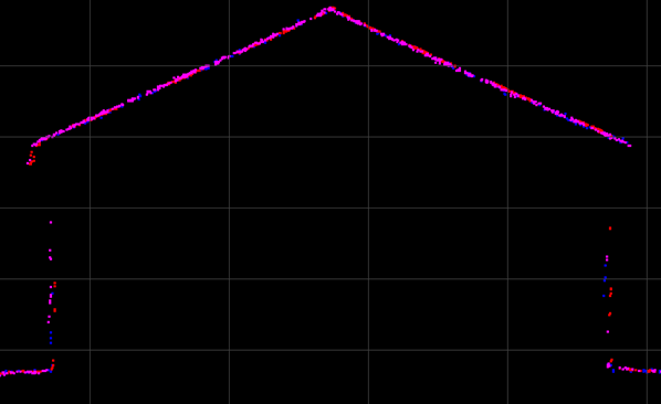
After this step we recommend continuing with the True View recommended workflow. Some of the steps recommended are “Smoothing“, “Control Points“, “Outliers removal” or “Ground Classification“.
