Field operations can be expensive and often have time limitations due to limited access, weather, or even specific temporal ranges specified by a client. For these reasons you should always perform TrueView 3DIS field data checking for production datasets. It is usually more efficient to fly another a survey immediately rather than reschedule. If you have a problem that you cannot diagnose GeoCue support will take in-field support calls during normal business hours or typically respond to a summitted ticket with 4 business hours. These steps are ordered by both importance and required time. Steps 1-7 are relatively quick and can give you reasonable assurance you are leaving the field with good data. Steps 8-10 require an LP360 Drone license but will give you complete assurance you have a good dataset.
- TrueView Web UI or Controller Box Codes and Messages: Pay close attention to the TrueView Web UI or controller box LEDs and LCD read-out messages during initialization and wind down. Refer to the LED tables in the applicable hardware users guide for the specific meaning of messages. Upon landing be especially aware of a red GNSS LED indicating a comprise of your GNSS quality. Also be aware if any step in the initialization or winddown processes stall at a certain step or take an excessive amount of time. If you experience any behavior which you cannot diagnose from the TrueView Web UI or LED tables, contact GeoCue Support.
- Cycle Logs: (Skippable if using Step 7) After winddown insert the UMS into your computer. Navigate to the \Cycle_YYMMDD_hhmmss\System folder and open the CycleLog.csv or system.log in a text editor (Notepad ++ is a freeware application with color coding for good readability). Search the file (Control+F) for WARNING, ERROR, and FAIL as these entries may indicate issues that may comprise your data, contact GeoCue Support if you are not sure how to troubleshoot these messages.
You can also create a batch file that will search and print WARNING, ERROR, and FAIL messages. Paste the below code into a text file and save it as CycleLogChecker.bat, then drag-and-drop the CycleLog.csv onto the batch file, a console window will appear and it will print out line containing WARNING, ERROR, or FAIL if they exist.
findstr /I /N “Fail Warning Error” %1
Pause
If you would like the batch to output the error messages to another file use:
findstr /I /N “Fail Warning Error” %1 > CycleLogErrors.csv
Pause - Image Count: (Skippable if using Step 7) Open the folders for Cycle_YYMMDD_hhmmss/Flight_YYMMDD_hhmmss/Camera# folder and count the number of images. While inside a folder in Windows Explorer the file count will be displayed in the lower left corner. The image counts between all Camera folders should match or be no more than a few images different. If there is a large discrepancy you may have experienced camera errors.
- Image Quality: You can spot check photos for each camera to ensure photos are not blurry or overexposed. Blurry photos can happen during low altitude flights, slowing down from 5 m/s to 4 m/s or even slower may eliminate blurring. The shutter speed can also be manually set in the CoreConfiguration.json file, refer to the TrueView manual for more details on manually setting camera parameters.
- Lidar data size: Inspect the folder Cycle_YYMMDD_hhmmss/Flight_YYMMDD_hhmmss/Laser1 there should be a large file named laser.udf or laser.bin that for most typical flights should be over 1GB. For higher end Riegl systems, such as the TV680 or TV720, there will be several RXP files with the first ones being 4GB and the last one being <4GB. In all cases if the files are small or even zero kb you may have an error with your lidar sensor.
- TVDataCheck.exe: (True View 410 only) This utility will scan the file for time interval gaps or spin reversals. The TVDataChecker is delivered with LP360 in the %CommonProgramFiles%\LP360 folder. It will also produce a log file in the Laser1 folder. GeoCue may request this file if you notice any errors with your laser.bin. See TVDataChecker for more information on using and analyzing the results from this utility for your TV410.
- Import Cycle to LP360 Drone, formerly called TrueView EVO: (If you have roamed an LP360 EVO Explorer license or have internet connectivity to obtain one) The import process for LP360 Drone, formerly called TrueView EVO, by its nature, will check your dataset while it imports. The most obvious error would be if you flight plan does not match how you programmed it in your flight controller software which may indicate a GNSS heartbeat error with your system. If you encounter any errors during import that you cannot diagnose, please contact GeoCue Support.
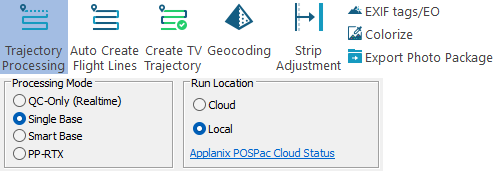
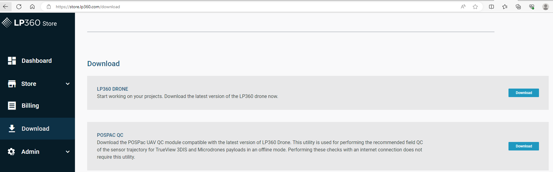
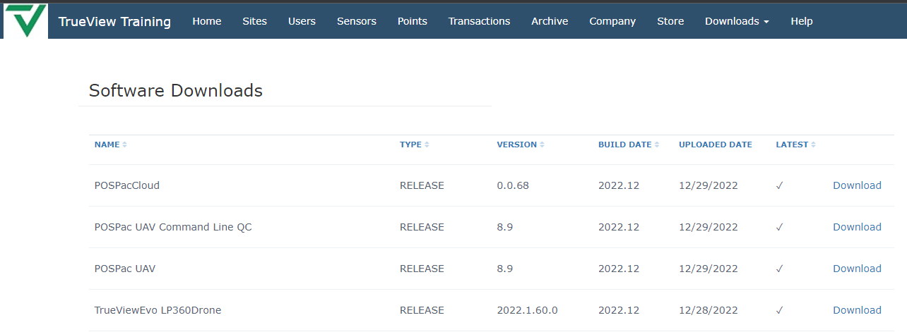
- Process your QC-Only (realtime) sensor trajectory with the POSPac CLI QC Utility or post process your sensor trajectory: (If you have roamed an LP360 Drone license or have internet connectivity to obtain one) In LP360 v2022.1.60.0, we released the Realtime Trajectory QC tool for TrueView 3DIS field data checking. This tool allows for creating a geocoded point cloud using an RNAV solution instead of an SBET solution. The resultant dataset is not intended for final processing but is a handy tool in the field since you can create a point cloud from a flight without needing a complete PPK solution. There are several use cases where this can be a great tool to save time since you can quickly determine if there is sufficient coverage, reflectance, canopy penetration, checkpoint coverage, GNSS slips during flight, and even check colorization results. The cloud runner of this tool comes with any installation of LP360 v2022.1.60.0 or later, but an offline utility exists for download from your Reckon account under the Downloads -> Software -> POSPac UAV Command Line QC or free from the LP360 Portal, under Download -> POSPac QC. The Realtime QC tool can be accessed by importing any cycle into a new LP360 project and, within the POSPac dialogue box, selecting “QC-Only (Realtime).” The Realtime QC will produce a POSPac-style QC report that can be used to determine sufficient GNSS coverage, estimated trajectory solution, and correct estimated flight length. The full POSPac report is unavailable until final processing in a PPK-corrected format. Review the POSPac QC Report. At a minimum, inspect the L2 Satellite Lock/Elevation graph for cycle slips, and the Top View of the realtime trajectory information that it matches the flight path you planned and reflects what shows in your imported data. If you have post processed the sensor trajectory, then also inspect the GNSS QC Statistics for at or near 100% fixed rate, as well as generally consistent satellite count on the graph. And the Smoothed Performance Metrics: Position Error RMS should be within horizontal and vertical tolerances of your sensor and not have any large spikes indicating a loss of accuracy.
- Inspect a Point Cloud Profile: (If you completed the POSPac QC or post processing successfully) Process through to Geocode and colourize your point cloud. Then, review the coverage and colourization. Draw a profile over a uniform surface such as a roof top, parking lot or a flat well maintained paved road. Change the coloring to Point Source ID inspect for flight line misalignment or excessive point cloud noise. Keep in mind the realtime data is expected to have misalignment, but not missing data coverage.
- QC checkpoint Z values: (If you completed the POSPac post processing successfully) A final assurance that your point cloud is correct is to inspect the Z value statistics for your check points. Your RMSE should not exceed the rating for your sensor. If you have a large RMSE with a closely matching Mean Error you likely have a bias which is typically caused by improper pole heights with survey equipment, mismatches with geoids, or incorrect lever arm offsets. If you have a large error range first ensure that your check points were not obstructed during survey, if so turn off compromised check points. If a large error range still remains the other common occurrence is that you had a GNSS quality is during the flight or your sensor did not download the correct calibration, or there is a malfunction with your sensor and the calibration is no longer valid.
Note: Step 7 only requires an LP360 EVO Explorer, formerly TrueView EVO Explorer, license or higher for processing. For the more in-depth QC solution, steps 8 – 10 require an LP360 Drone, formerly TrueView EVO, license for these processing steps.